• To anyone looking to acquire commercial radio programming software:

    Please do not make requests for copies of radio programming software which is sold (or was sold) by the manufacturer for any monetary value. All requests will be deleted and a forum infraction issued. Making a request such as this is attempting to engage in software piracy and this forum cannot be involved or associated with this activity. The same goes for any private transaction via Private Message. Even if you attempt to engage in this activity in PM's we will still enforce the forum rules. Your PM's are not private and the administration has the right to read them if there's a hint to criminal activity.

    If you are having trouble legally obtaining software please state so. We do not want any hurt feelings when your vague post is mistaken for a free request. It is YOUR responsibility to properly word your request.

    To obtain Motorola software see the Sticky in the Motorola forum.

    The various other vendors often permit their dealers to sell the software online (i.e., Kenwood). Please use Google or some other search engine to find a dealer that sells the software. Typically each series or individual radio requires its own software package. Often the Kenwood software is less than $100 so don't be a cheapskate; just purchase it.

    For M/A Com/Harris/GE, etc: there are two software packages that program all current and past radios. One package is for conventional programming and the other for trunked programming. The trunked package is in upwards of $2,500. The conventional package is more reasonable though is still several hundred dollars. The benefit is you do not need multiple versions for each radio (unlike Motorola).

    This is a large and very visible forum. We cannot jeopardize the ability to provide the RadioReference services by allowing this activity to occur. Please respect this.

AM Carrier Signal Interference on Freight Trains - Tranmission line

Kilbum

Member
Joined
Aug 14, 2024
Messages
10
Hi All,

I am new to this forum and, although trained as a radio fitter mechanic, it has been decades since I delved into anything radio-related.
Please bear with me as I reacquaint myself with these concepts.;)

Context:
  • Application: AM carrier signal applied to a 230VDC power line on freight trains (1-2 km length).
  • Continuous power cable powering each device in parallel.
  • Network: Over 50 devices with unique addresses along the transmission line.
  • Data Transmission: All data sent on a 132.5 kHz carrier.
Issues Observed - Crosstalk Between Trains:
Reported Cause: Transmission passing from one train to another via the rails, through the earth’s surface, and into an adjacent rail.

My Thoughts:
  • Considering the resistance factors of wheel bearings, axle couplings, and the earth’s surface, this pathway seems unlikely.
  • I suspect EMI/RFI from each train, especially since trains are usually within 2 meters of each other.
  • Many faults (so-called crosstalk) occur when the 230VDC power is first applied or when trains are close together or passing at low speeds.

Shielding and Grounding Issues:
My Military training (Navy and Aerospace) taught me to bond shielding at both ends and use proper multipoint grounding.
  • Current Practice:
  • Each wagon’s cable shielding is not passed to the next wagon, creating isolated shields bonded at only one end.
    • Concerns:
      • High resistance through the coupling.
      • No wagon cable shields are connected
Terminology:
Crosstalk vs. Interference: I believe the term “crosstalk” is used too liberally. The issue seems to be interference, leading to communication loss rather than true crosstalk.

Objective:
  • Goal: Identify and verify the source of interference, then apply the best mitigation techniques to reduce or eliminate these events.
  • Testing: Building a small Arduino-based AM transmitter and a suitable 5W amplifier to induce fault events by transmitting adjacent to the cables.
Questions:
  1. Inducing Interference: What other methods or tools can I use to induce noise onto the carrier frequency to cause communication loss?
  2. Shielding Practices: Based on the latest evidence, should I consider grounding the shield at both ends to improve EMI/RFI mitigation? I believe this link is a good place to start : low-impedance path for interference currents
  3. Mitigation Techniques: What are the best practices for mitigating EMI/RFI in such a setup?
  4. OTS :Do you know of a portable off the shelf transmitter around maximum 10W that I could use to upset this carrier if indeed it is RFI
I truly hope that there is someone that has the knowledge to guide me down the right rabbit hole

Thank you in advance
 

AM909

Radio/computer geek
Premium Subscriber
Joined
Dec 10, 2015
Messages
1,258
Location
SoCal
Quick initial thought: what exactly is the "transmission line", i.e., a twisted pair of 12-gauge insuated stranded or coaxial or ...?

132.5 kHz is 2264m wavelength, so unshielded lines over a couple hundred meters are in the ballpark of being an antenna.
 

RFI-EMI-GUY

Member
Joined
Dec 22, 2013
Messages
7,350
Wow. AM modulation instead of FM? How quaint. And I suppose it it is not practical to have a train specific ID in each system because train cars must be interchangeable.

Yeah AM909 hit the nail on the head.

What about the common circuit used to power these devices? Why can't the communications occur on that circuit?

Can you provide a simplified drawing of the grounding arrangement now used?

If the carrier current leaks to the wheels, noise, track and earth, so can noise from those to disrupt the communications. The result is more RF power required to communicate, and thus more unwanted radiated signal. What does the 230 VDC power? Are those loads noisy? Areyou suggesting the 230 VDC returns through noisy train car couplers nott a separate ground conductor?

As far as a transmitter,the frequencies sound close to those for near field and RFID tags. There should be hardware and designs available to make a simple design. Not sure why you want to introduce disruption, when what you can more easily do is measure what the system radiates.
 

Kilbum

Member
Joined
Aug 14, 2024
Messages
10
Quick initial thought: what exactly is the "transmission line", i.e., a twisted pair of 12-gauge insuated stranded or coaxial or ...?

132.5 kHz is 2264m wavelength, so unshielded lines over a couple hundred meters are in the ballpark of being an antenna.
Hi thanks for the response
the Transmission line is exactley as you state although is twisted twin 8mm2 insulated.
 

RFI-EMI-GUY

Member
Joined
Dec 22, 2013
Messages
7,350
Hi thanks for the response
the Transmission line is exactley as you state although is twisted twin 8mm2 insulated.
Is twisted pair carrying DC? Is the return electrically isolated from the vehicle frame/ground? Can the signals be imposed on the two conductors in a balanced manner to eliminate common mode currents? Are the conductors shielded?
 

Kilbum

Member
Joined
Aug 14, 2024
Messages
10
Hi All,

I am new to this forum and, although trained as a radio fitter mechanic, it has been decades since I delved into anything radio-related.
Please bear with me as I reacquaint myself with these concepts.;)

Context:
  • Application: AM carrier signal applied to a 230VDC power line on freight trains (1-2 km length).
  • Continuous power cable powering each device in parallel.
  • Network: Over 50 devices with unique addresses along the transmission line.
  • Data Transmission: All data sent on a 132.5 kHz carrier.
Issues Observed - Crosstalk Between Trains:
Reported Cause: Transmission passing from one train to another via the rails, through the earth’s surface, and into an adjacent rail.

My Thoughts:
  • Considering the resistance factors of wheel bearings, axle couplings, and the earth’s surface, this pathway seems unlikely.
  • I suspect EMI/RFI from each train, especially since trains are usually within 2 meters of each other.
  • Many faults (so-called crosstalk) occur when the 230VDC power is first applied or when trains are close together or passing at low speeds.

Shielding and Grounding Issues:
My Military training (Navy and Aerospace) taught me to bond shielding at both ends and use proper multipoint grounding.
  • Current Practice:
  • Each wagon’s cable shielding is not passed to the next wagon, creating isolated shields bonded at only one end.
    • Concerns:
      • High resistance through the coupling.
      • No wagon cable shields are connected
Terminology:
Crosstalk vs. Interference: I believe the term “crosstalk” is used too liberally. The issue seems to be interference, leading to communication loss rather than true crosstalk.

Objective:
  • Goal: Identify and verify the source of interference, then apply the best mitigation techniques to reduce or eliminate these events.
  • Testing: Building a small Arduino-based AM transmitter and a suitable 5W amplifier to induce fault events by transmitting adjacent to the cables.
Questions:
  1. Inducing Interference: What other methods or tools can I use to induce noise onto the carrier frequency to cause communication loss?
  2. Shielding Practices: Based on the latest evidence, should I consider grounding the shield at both ends to improve EMI/RFI mitigation? I believe this link is a good place to start : low-impedance path for interference currents
  3. Mitigation Techniques: What are the best practices for mitigating EMI/RFI in such a setup?
  4. OTS :Do you know of a portable off the shelf transmitter around maximum 10W that I could use to upset this carrier if indeed it is RFI
I truly hope that there is someone that has the knowledge to guide me down the right rabbit hole

Thank you in advance
*** Update in order to answer a few questions together and add clarity ***

ECP 230VDC Trainline Power Cable

The Electronically Controlled Pneumatic (ECP) trainline power cable is a fascinating component in modern rail systems. Here are the key points:
  1. Dual Purpose:
    • The ECP power cable serves a dual role:
      • Power Supply for Braking System:
        • It provides power to the train’s braking system, specifically the brake control units.
      • Network Communication:
        • Simultaneously, it acts as the network cable for communication.
        • A carrier signal (data) rides along this same power cable, allowing instructions to be sent and current status information to be retrieved from various devices.
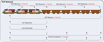
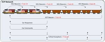
  2. Network Architecture:
    • In the ECP system:
      • Locomotive (HEAD END UNIT or HEU):
        • The locomotive functions as the main switch or router, essentially serving as the brain of the operation.
      • Train Cars (Wagons) as Individual Nodes:
        • Each train car becomes an individual node in the network.
        • Each car has a unique programmed ID known as a Car Control ID (CCID).
      • Network Re-sequencing:
        • When the locomotive changes (e.g., during train configuration adjustments), the network re-sequences to account for all CCIDs.
        • This flexibility allows wagons/cars to be swapped around on the network and then reassigned to the new train setup.
  3. Industry Challenges:
    • The rail industry faces misconceptions and challenges:
      • Expertise Gap:
        • Many industry professionals are mechanical fitters and mechanical engineers.
        • Their understanding of topics like Electromagnetic Interference (EMI) and Radio-Frequency Interference (RFI) may be limited.
      • Debunking Myths:
        • It’s essential to debunk assumptions like “they designed it that way, so they must know what they’re doing.”
      • Crosstalk and Interference:
        • Demonstrating the impact of crosstalk (interference) is crucial.
        • Addressing this issue can prevent disruptions and improve overall system reliability.
      • Rectification Costs:
        • Rectifying problems in the rail industry can be expensive, with costs sometimes exceeding 100 million dollars.
 

Kilbum

Member
Joined
Aug 14, 2024
Messages
10
Wow. AM modulation instead of FM? How quaint. And I suppose it it is not practical to have a train specific ID in each system because train cars must be interchangeable.

Yeah AM909 hit the nail on the head.

What about the common circuit used to power these devices? Why can't the communications occur on that circuit? ...... It Does

Can you provide a simplified drawing of the grounding arrangement now used?

If the carrier current leaks to the wheels, noise, track and earth, so can noise from those to disrupt the communications. The result is more RF power required to communicate, and thus more unwanted radiated signal. What does the 230 VDC power?
The DC power is used to power all the devices along the train, most operate at around 76VDC, i gather the 230VDC was used to compensate for voltage losses along the enormous length of a train..
** you also jolted another memory from long ago, if the wavelength for 132.5khz, is 2200m. then most trains are at 1/2 wavelength long... hmmm

Are those loads noisy? Areyou suggesting the 230 VDC returns through noisy train car couplers nott a separate ground conductor?

As far as a transmitter,the frequencies sound close to those for near field and RFID tags. There should be hardware and designs available to make a simple design. Not sure why you want to introduce disruption, when what you can more easily do is measure what the system radiates.

Is twisted pair carrying DC? Is the return electrically isolated from the vehicle frame/ground? Can the signals be imposed on the two conductors in a balanced manner to eliminate common mode currents? Are the conductors shielded?
Details of the power isolation and conductor shielding in the ECP trainline system:
  1. Power Isolation:
    • The ECP trainline power and Carrier cable achieves 100% isolation, meaning there is no direct DC return bonding to the ground plane.
    • Continuity testing demonstrates that the isolation exceeds 200 megohms between the wagon body (referred to as “ground”) and the DC negative (“return”).
  2. Conductor Shielding:
    • Each conductor is not independently shielded.
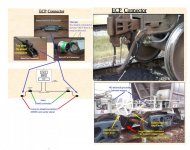
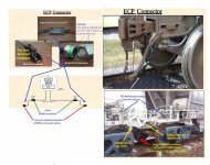
    • The outer layer of the cable has a shield, but it is only connected to the wagon body at one end.
    • Importantly, this shield is not passed across wagons to bond them at the same potential.
    • Instead, there is a break in the shield connection between each wagon.
    • For instance, in a 100-wagon train, there are 100 breaks in the shield bonding!
  3. I recommend reviewing the attached images for a visual representation of this configuration.

yep already read all this - but no science behind their paper.
See attached - This is a paper from chinese PHD's that are inline with my thoughts of boding and grounding at both ends :
 

Attachments

  • Intercar connection cables.jpg
    Intercar connection cables.jpg
    131.3 KB · Views: 8
  • ECP network setup.jpg
    ECP network setup.jpg
    7.2 KB · Views: 10
  • Intercar connection cables.jpg
    Intercar connection cables.jpg
    131.3 KB · Views: 9
  • ECP network setup.jpg
    ECP network setup.jpg
    7.2 KB · Views: 12
  • Analysis of Frequency Study Domain Characteristics of Crosstalk.pdf
    872.1 KB · Views: 2
Last edited:

RFI-EMI-GUY

Member
Joined
Dec 22, 2013
Messages
7,350
6.7 Crosstalk
Crosstalk is the unwanted coupling of ECP communications between two adjacent Trains and
has been experienced across Networks once the density of ECP train operations increases.
The mitigation for crosstalk has been to update the communication protocols so that each Train
has unique network addresses for HEUs, CCDs, PSCs and EOTs.
All ECP installations shall have their software updated to provide for unique network addresses


Kilbum

Member
Joined
Aug 14, 2024
Messages
10
I have thoroughly researched the standards and OEM information related to the ECP system. I have a lot skepticism regarding their ability to address crosstalk is understandable, especially given the persistent issues over the past 18+ years.
  • Their approach of adding a timeout delay to mitigate the problem seems like a band-aid solution rather than a comprehensive engineering fix.
  • The fundamental issue of penetration and radiation within the so-called shielded cable remains unaddressed.
My observation about old concepts growing without rigorous engineering scrutiny is based around, the email responses I have received from the OEM's.

Sometimes, revisiting established practices with fresh eyes can lead to innovative solutions and fix the misconceptions of the past.
 

RFI-EMI-GUY

Member
Joined
Dec 22, 2013
Messages
7,350
If there is some hesitation in the industry about grounding and bonding a far end of a shielded cable due to some concern about DC ground loops or noise, it is possible to construct a bandpass filter at the specific 132.5 KHz frequency to shunt the RF without passing DC or other noise frequencies.
 

Kilbum

Member
Joined
Aug 14, 2024
Messages
10
If there is some hesitation in the industry about grounding and bonding a far end of a shielded cable due to some concern about DC ground loops or noise, it is possible to construct a bandpass filter at the specific 132.5 KHz frequency to shunt the RF without passing DC or other noise frequencies.
My understanding of the laws of physics, especially electromagnetic theory has been derived from my time in the Navy and working for Boeing and BAE systems in Radar/Radio maintenance - systems engineering

Proper Bonding Solutions:
  • Shield Bonding: Connecting metallic shields to a common ground minimizes ground loops. This ensures that induced currents have a low-resistance path to dissipate.
  • Multipoint Bonding: Bonding at multiple points along the shield provides redundancy. Even if one connection fails, others maintain proper grounding.
  • Low Resistance: Achieving low resistance, around 0.1 ohm is essential. Proper bonding reduces voltage differentials and minimizes ground loop effects.

Aerospace Applications:
In aircraft like the F18 Hornets that i worked on, proper bonding is critical. Avionics systems, communication equipment, and navigation instruments rely on effective grounding.
  • Multipoint Shield bonding prevents interference from external sources (such as radar or radio signals) that would induce and ensures reliable operation.
Is there something that I am not getting, because everything in their shield design goes against what I was taught
see link that validaites thoughts low-impedance path for interference currents
The EMC standards site refutes on correctly bonded systems DC ground loops or noise

extract from document on this subject
attached document
"Analysis of Frequency Domain Characteristics of Crosstalk for Train Network Control Communication Cable"
6 CONCLUSION
The root cause of crosstalk is the distribution parameters between cables, which are affected by such factors as the relative position of
cables, coupling length, interference source frequency, and grounding mode of shielding layer. The simulation results show that the
crosstalk on communication cable can be reduced by adopting the following measures.

In the limited space of the train, spacing between interference line and communication cable greater than 100mm is appropriate. Communication cables should be arranged as close as possible to the car body or the public grounding plane such as the cable trough. If restricted by the layout of on-board electrical equipment, the coupling length of interference line and communication line should be reduced as far as possible. With the increase of frequency, both metal loss and medium loss increase rapidly.

And the transverse size of the transmission line cannot be ignored compared with the wave length. The coupling between circuits becomes more serious.
Therefore, communication cables should be wired away from high-frequency radiation areas as far as possible, such as traction and auxiliary converters. The shielding layer of the communication cable shall be double-grounded. These measures have certain engineering application value to guide the communication cable wiring of train network control system.


see attatched
 

Attachments

  • Analysis of Frequency Study Domain Characteristics of Crosstalk.pdf
    872.1 KB · Views: 6
Last edited:

RFI-EMI-GUY

Member
Joined
Dec 22, 2013
Messages
7,350
I am curious as to how the signal is imposed on the DC conductors. Is the RF balanced? If so, how is the DC conductor isolated (RF wise) from the chassis/frame ground? Is the RF truly balanced? If the signal is well balanced and terminated into a corresponding impedance at end of line, the radiation should be minimized.

You could rig up a train and a receiving station, consisting of a Spectrum analyzer and some sort of corresponding dipole antenna, to measure the signal received with a "normal" configuration, and then bond each car with a jumper cable to the next to see if the signal substantially reduces. Note that in "normal" state, the couplers should be providing some level of bonding, but if the train is slowing or stopped, there would be slackness * and thus the bonding would be less effective than when in motion.

* Jr, Bob Dodds.
1723848710382.png
Y
 

Kilbum

Member
Joined
Aug 14, 2024
Messages
10
I am curious as to how the signal is imposed on the DC conductors. Is the RF balanced? If so, how is the DC conductor isolated (RF wise) from the chassis/frame ground? Is the RF truly balanced? If the signal is well balanced and terminated into a corresponding impedance at end of line, the radiation should be minimized.

You could rig up a train and a receiving station, consisting of a Spectrum analyzer and some sort of corresponding dipole antenna, to measure the signal received with a "normal" configuration, and then bond each car with a jumper cable to the next to see if the signal substantially reduces. Note that in "normal" state, the couplers should be providing some level of bonding, but if the train is slowing or stopped, there would be slackness * and thus the bonding would be less effective than when in motion.

* Jr, Bob Dodds.
View attachment 167677
Y
Both Trainline DC conductors are 150Meg Conducter-Ground(wagon body) so very much isolated
...................
here’s my testing strategy: I’ve got this tiny spectrum analyzer (SA Ultra) that I’m hoping can cover the LF and MF bands.
My goal is to monitor the Trainline conductor and carrier for any real radio frequency interference (RFI) during crosstalk events.

Now, I just need to figure out how to set up the TinySAultra with a fanless PC for continuous data logging. I’ll also look to others to write a program to clear out old files after 3 days to prevent memory overload.

Thinking of getting an analog data logger too
what do you think?

as for the other

I am considering enhancing the shielding and mitigating electromagnetic interference (EMI) By:
  1. Aluminium Mesh Wrapped Shielding: Wrapping the cable or connection points with an aluminium mesh provides effective RFI, EMI protection.
  2. Ferrite Clamps: will hopefully, suppress high-frequency noise by absorbing it within the ferrite material.
  3. Exponential Bonding: Our Team will ensure proper bonding between shield points, Exponential bonding involves connecting all open-ended shield points to the wagon bodies. This helps maintain a consistent ground reference and reduces RFI, EMI.
  4. Contenary Strap: Adding a contenary strap (a flexible conductor) between adjacent wagons ensures electrical continuity. It helps prevent voltage differences, plus eliminates the so called "ground loops" and minimizes EMI between connected components.
 

RFI-EMI-GUY

Member
Joined
Dec 22, 2013
Messages
7,350
I would consider making a bandpass filter for your 132.5 KHz signal to put between the tiny SA and antenna. You might be surprised how easily any spectrum analyzer becomes overloaded by out of band signals, LW,MW,HF broadcast etc.
 

RFI-EMI-GUY

Member
Joined
Dec 22, 2013
Messages
7,350
I am curious how the system contends with interference in normal operation. If brakes are being applied, is there a continuous and/or redundant data transmission in case of disruption? Have there been failures or accidents?
 

Kilbum

Member
Joined
Aug 14, 2024
Messages
10
I am curious how the system contends with interference in normal operation. If brakes are being applied, is there a continuous and/or redundant data transmission in case of disruption? Have there been failures or accidents?

We have what they determined ECP "Crosstalk events" and "CrossTalk Penalties"
"Crosstalk Events" Low level interference, maybe a spike or surge. causes no issue except logging in file an issue with comms
"CrossTalk Penalties" This refers to a significant interference issue that lasts longer than 6 seconds.
If the interference event exceeds 6 seconds, it triggers an emergency response, which stops the train.
Initially, the threshold was set at 3 seconds, but due to increasing incidents of crosstalk-related problems, they implemented mitigation software.
This software adjusts the delay before an emergency fault occurs, helping manage crosstalk issues more effectively.

  1. Normal Operation:
    • When the engineer applies the brakes, the ECP system electronically signals all train cars to brake simultaneously.
    • Unlike traditional braking, where each car brakes individually, ECP prevents excessive in-train forces and reduces stopping distances.
    • The brake pipe is not depleted during application; it remains charged.
  2. Emergency Application:
    • In emergencies, all brake reservoir pressure is released instantly.
    • If there’s a crosstalk or interference event lasting more than 6 seconds, this emergency release occurs.
    • It can about 40 minutes for the train to rebuild brake pressure afterward.
 

Kilbum

Member
Joined
Aug 14, 2024
Messages
10
I would consider making a bandpass filter for your 132.5 KHz signal to put between the tiny SA and antenna. You might be surprised how easily any spectrum analyzer becomes overloaded by out of band signals, LW,MW,HF broadcast etc.

Major Interference Issue:
  • As I believe we’re dealing with a significant interference problem that lasts more than 6 seconds and this issue affects the train’s performance. I was thinking of connecting a spectrum analyzer to the train’s DC conductors (capacitively coupled) by doing this, we can observe any signals that appear on the conductors and identify the frequencies and levels causing the penaltie/ major faults
  • Additionally, we should monitor the shield of the poorly grounded train wagons. This will help us understand how interference affects the wagon body or if it plays a part of the issue.

Monitoring the 132.5 kHz Carrier:
We want to check if there’s an additional 132.5 kHz carrier interfering with the trainline. To capture this signal, I can use an analog signal logger specifically designed for recording continuous signals. Even if you haven’t used one before.

I would have prefered to record oscilloscope data the after the event review.
 
Top