antenna feedline impedance

Status
Not open for further replies.

VA3CQA

Member
Joined
Sep 14, 2014
Messages
24
Location
Scarborough Ontario Canada
The attached antenna plans call for a feedline length of at least 1/2 wavelength before the line bends toward the radio. What if i didnt have a 1/2 wavelength would it be negligent or very bad for the antenna?..also the attachment seems sloppy in the pic shouldnt the leads be kept as close as possible?

content://com.sec.android.app.sbrowser/readinglist/0912104118.mhtml
 

AK9R

Lead Wiki Manager and almost an Awesome Moderator
Super Moderator
Joined
Jul 18, 2004
Messages
9,342
Location
Central Indiana
You will have to attach your file to a post. We can't see files on your smart phone.
 

VA3CQA

Member
Joined
Sep 14, 2014
Messages
24
Location
Scarborough Ontario Canada
Sorry my bad...hopefully ive posted some pics now
 

Attachments

  • WB0TGE-Image-A.jpg
    WB0TGE-Image-A.jpg
    20.7 KB · Views: 1,411
  • WB0TGE-Image-C.jpg
    WB0TGE-Image-C.jpg
    33.3 KB · Views: 1,470
  • WBØTGE-Mighty-Woof-2m_440-DBFD-Antenna.jpg
    WBØTGE-Mighty-Woof-2m_440-DBFD-Antenna.jpg
    12.3 KB · Views: 2,608

prcguy

Member
Joined
Jun 30, 2006
Messages
15,323
Location
So Cal - Richardson, TX - Tewksbury, MA
For vertical pol VHF/UHF use you would want the feedline to head away from the antenna at a right angle as far as possible to avoid disturbing the omni directional pattern. That may be the reason for their half wave feedline comment and I dont see any reason to do that for matching.
prcguy
 

prcguy

Member
Joined
Jun 30, 2006
Messages
15,323
Location
So Cal - Richardson, TX - Tewksbury, MA
I also see a slight problem in the finished antenna pic with the pigtails coming off the coax and attaching to the feedpoint. The pigtails become part of the antenna and if too long will make the entire antenna too long. I would make them just long enough to reach the feedpoint.
prcguy
 

VA3CQA

Member
Joined
Sep 14, 2014
Messages
24
Location
Scarborough Ontario Canada
I had the pigtail length being too long also but i never even thought of the radiated pattern being affected by a feedline... thank you for that...i thought thats why cable is sheilded though so it doesnt affect the field?
 

FeedForward

Member
Joined
Jul 7, 2014
Messages
75
The primary reason for coax as a transmission line is that it is the most convenient way to get RF to an antenna.

FF
 

prcguy

Member
Joined
Jun 30, 2006
Messages
15,323
Location
So Cal - Richardson, TX - Tewksbury, MA
The feed line ends when it splits and heads opposite directions and even though the pigtails are made from the coax they will add length to the elements and radiate.
prcguy

I had the pigtail length being too long also but i never even thought of the radiated pattern being affected by a feedline... thank you for that...i thought thats why cable is sheilded though so it doesnt affect the field?
 

cmdrwill

Member
Joined
Mar 30, 2005
Messages
3,984
Location
So Cali
Most radios are set up for 50 ohm antennas, RG213 is the perfered cable, Mini RG8X is next, with RG58A/U used in most mobile installations.

the coax cable is the second most important part of the antenna system, don't scrimp.....
 

cmdrwill

Member
Joined
Mar 30, 2005
Messages
3,984
Location
So Cali
I forgot to mention, the J pole type antennas radiate from the feed line, coax, also. As the one dipole mentioned, it is NOT 50 ohms. That is why the loop in the coax is there to reduce radiation from the feed line.

As you can see I am NOT a fan of J pole antennas, I think my many years on antenna testing ranges helps....
 
Last edited:

ramal121

Lots and lots of watts
Premium Subscriber
Joined
Dec 5, 2008
Messages
2,121
Location
Calif Whine Country
I forgot to mention, the J pole type antennas radiate from the feed line, coax, also. As the one dipole mentioned, it is NOT 50 ohms. That is why the loop in the coax is there to reduce radiation from the feed line.

As you can see I am NOT a fan of J pole antennas, I think my many years on antenna testing ranges helps....

Well for one, this is NOT a J-pole. It's a simple two band fan dipole, and I would suspect it would be a reasonable match in the 50 ohm neighborhood (once the feedpoint is cleaned up a little). While not a spectacularly performing antenna, I would imagine the bandwidth is pretty good.

Even with a well matched antenna, a choke never hurts in case there are induced currents to the outside of the coax.
 
Last edited:

VA3CQA

Member
Joined
Sep 14, 2014
Messages
24
Location
Scarborough Ontario Canada
Thanx ramal121...im located in toronto ontario so repeaters are everywhere....this will be used on a 5 watt handheld....right now the radio has a 40cm jetstream that replaced the stock rubber duck which works fine but reports say im a little scratchy....im hoping this antenna mounted outdoors will help
 

ramal121

Lots and lots of watts
Premium Subscriber
Joined
Dec 5, 2008
Messages
2,121
Location
Calif Whine Country
Ok, let me drawl on something about antennas. There's nothing magical about them, just plain physics.

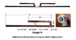
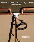
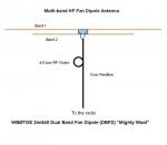
You have a handheld with a rubber duck antenna. Convenient and portable yes. The best to use, no. The best way to describe a rubber duck would be a negative gain antenna. Some are good, others are just horrible. Building an external antenna can increase your signal output. The easiest thing to build is a dipole (as shown above) or a quarter wave ground plane and normally referred to as a unity gain antenna. Just using that will help your signal out by a minimal amount even though it would be close to the handheld inside.

These are easy to build and if you stick to published dimensions it should be in the ball park without any fancy testing.

Now what if you want an antenna that gives you a little gain. Agreed this will help, but building it becomes more complicated and you really don't know if it's tuned and preforming correctly unless you invest in some kind of test gear that would tell what it's actually doing. And for what? Maybe an omni antenna that would give you 2.5, 3, maybe 5dB if you're lucky. If you're into this this, go for it. Experiment and try different things. That's what this is all about. If it doesn't work out, toss it into the bone yard and try something different.

Now take that same unity gain antenna (1/4 wave ground plane or dipole) that is easy to build and you know it otta work, stick it outside on a pole maybe 15 or 20 foot up in the air with some good quality coax and I couldn't see why you wouldn't see a 5 to 10dB increase in signal strength over your rubber duck. Easy to do for increased coverage. That's what I'd do.

After that, then you could think about that high gain co-linear antenna you're going to build on that 75 foot tower you just set up in the back yard.
 
Last edited:

VA3CQA

Member
Joined
Sep 14, 2014
Messages
24
Location
Scarborough Ontario Canada
Lol...thanx im gonna give this a try i just bought all the parts so like you say ill give it a shot and toss it if i have to....i think i can get my hands on an analyzer to borrow to see if its performing well....for whatever its worth im gonna have fun building it....
 

Token

Member
Joined
Jun 18, 2010
Messages
2,379
Location
Mojave Desert, California, USA
I have used fan dipoles for many years, and I like them, however I have never tried one at VHF/UHF, I have always used them on HF.

Some people have trouble grasping the concept that it is really two antennas on a common feedpoint, and that the RF only "sees" the antenna for its band. I had one fairly new ham argue that such an antenna could not possibly be driven by or matched to 50 Ohm coax, because since each element was 50 Ohms the impedance was 25 Ohms to the coax (no concept of the differences with AC vs DC circuits). He (incorrectly) thought he understood it better when I started by telling him that dipoles are more like 73 Ohm impedance, but then when I described using 75 Ohm coax he took a turn for the worse ;)

One thing to keep in mind when trimming / adjusting fan dipoles, the elements do interact. Adjusting one band DOES affect the match of the other band. In general I always start by adjusting the lowest freq band first, although in this design I would not be surprised if you don't have to touch a thing.

T!
 

ramal121

Lots and lots of watts
Premium Subscriber
Joined
Dec 5, 2008
Messages
2,121
Location
Calif Whine Country
Token is absolutely correct. If multiple elements are connected to a single feedpoint, the one close to matching will work fine. This assumes that the other elements are so far out there in impedance they are not a factor (in college i was taught that if it's more than ten times, it doesn't exist).

Anyway, if you got the stuff, go for it. Just remember the antenna will have to be vertical for FM repeaters (DUH)! If the coax comes off the feed point and drops to the house, it being parallel to a radiating element will change the pattern off the antenna. You should indeed come off the feed point horizontal before it drops down. I'd like a full wavelength on 2M (6 foot). You stated a half wavelength. OK, the idea is whatever you can rig up. If you can scroung up a meter for SWR or reflected power you'll at least know if the transmitter will be happy. The more horizontal the better. The coiled choke is up to you. Good luck and have fun!
 
Last edited:
Status
Not open for further replies.
Top