Antenna for dummies for 315MHz RF Receiver?

Status
Not open for further replies.

ibrewster

Member
Joined
Feb 12, 2020
Messages
10
Location
Fairbanks, AK
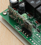
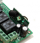
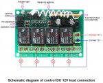
I hope this is a good place to post this question. I am building a receiver to use with the CarLink mirror in my car (so I can actually do something wit it other than just open the garage door). To that end, I picked up a 315MHz RF receiver like this one: https://www.amazon.com/4-Channel-Wireless-MELIFE-Transmitter-Receiver/dp/B07S51NBFF?th=1 (photo attached) From what I can tell, it's just a small RF receiver with a coil antenna, and a bunch of extra circuitry to interface with the relays and coded remotes.

I got everything hooked up and programed the way I wanted, and tested that it worked. Unfortunately, the range stank - I could be sitting in my car just outside the garage, and push the button, and the receiver just inside the garage would get nothing. Basically, it only seems to work reliably if there was absolutely nothing between the transmitter and receiver.

After doing some research, I found a number of posts claiming that coil antennas can be tricky to get right, so with nothing to loose I tried straightening the wire and pulling it outside of the (wooden) box I installed everything in. This did seem to help somewhat, and testing actually looked pretty good, but when I tried it from inside my car (using the mirror buttons or the handheld remotes), I was back to no real functionality - it would work if I had direct line of sight with no obstacles, but as soon as there was anything between transmitter and receiver, it was back to not receiving. Further research informed me that the "ideal" antenna length would be 23.81cm long, but that's about as far as I could get - the rest of my research turned up stuff about "dipole antennas" and connecting to the "ground plane", which I honestly don't understand. So that leaves me with a few questions I'm hoping can be answered here:

1) The current coil antenna, once straightened, appears to be about the right length, but a significant portion of it is still inside the container, surrounded by other electrical stuff I have crammed in there. Might putting a longer wire on, such that the 23.8cm could all be *outside* the enclosure help?

2) Regarding dipole/ground plane, is that as simple as attaching a second wire of the proper length to the ground connector of the receiver and run it outside the box, or is there more to it? Would that be likely to improve reception?

3) Might the receiver itself be the issue - that is, might I be able to improve the situation by using a different, higher-quality receiver module than what is on that board? I don't need the relays - all I need is to be able to generate a 4 channel digital output that I can feed into a micro controller (Specifically, a CherryPy). I'm not afraid of having to do a bit of programming, however.

At the end of the day, I don't need a huge range. I just need the device, sitting inside my garage, to be able to reliably pick up signals from my car at the end of the driveway (about 20 feet or so, clear line of sight). I wouldn't have thought that would be all that difficult, but what do I know? :)
610nOb9LsyL._AC_SL1001_.jpg
 

kruser

Well Known Member
Premium Subscriber
Joined
Nov 25, 2007
Messages
5,077
Location
W St Louis Cnty, MO
Can you supply photos of the inside of one of the transmitters and maybe one of the component side of the part they call the "Superheterodyne receiving mode" that the coily antenna is attached to from the receiver?
 

ibrewster

Member
Joined
Feb 12, 2020
Messages
10
Location
Fairbanks, AK
Are you sure the transmitter is putting out its full signal strength?
Can you supply photos of the inside of one of the transmitters
The primary transmitter that I am interested in is the mirror in my car, so I have no reason to think it's not working at full strength, and I can't very well take it apart to get photos of the inside :) I could certainly disassemble one of the handheld remotes, though, perhaps later tonight or this weekend.

and maybe one of the component side of the part they call the "Superheterodyne receiving mode" that the coily antenna is attached to from the receiver?
Ok, that's interesting. Apparently there are a couple of different configurations that, at first glance, look the same. The photos attached here are from the actual site/page that I ordered from, so they should be accurate, however I'll have to double-check when I get home to verify which style I actually got. I do notice that the Amazon link/photo I posted look slightly different, with the metal can on the one side rather than the green coil on the other.
Screen Shot 2020-02-13 at 8.03.35 AM.pngScreen Shot 2020-02-13 at 7.59.42 AM.png
 

ibrewster

Member
Joined
Feb 12, 2020
Messages
10
Location
Fairbanks, AK
Rather than the antenna, it -might- be the receiver that's lacking. You could try adding an amp to boost the signal from the remote.. They make cheap ones 1PC 50-4000MHz RF Low Noise Amplifier LNA 50-4000MHz SPF5189Z NF = 0.6dB 7426925371316 | eBay

I actually tried one similar to this for listening to SSB and CW signals on 432 Mhz. It did make a difference.
Looks like it could be worth a shot. Just have to figure out exactly where to solder the antenna leads, since that has actual connectors, whereas my system just has a single wire/attachment point.
 

ibrewster

Member
Joined
Feb 12, 2020
Messages
10
Location
Fairbanks, AK
One additional thought - could it be as simple as how I have the antenna oriented (horizontal vs vertical)? Maybe I just have things oriented in such a way that it only works well from certain angles, and that's why it worked a bit in testing, but not in "the real world", as it were?
 

a417

Active Member
Joined
Mar 14, 2004
Messages
4,669
I extended garage doors with similar recievers for some rescue stations. The garage door openers were deaf, and crews had to sit IFO the bays just outside the apron and wait to close the doors (due to the cheap remote senders being mounted in-front of giant vertical aluminum body panels, making them massively directional).

I took LMR200, and removed the stock wire antenna coil on the recievers. Due to this being a one time installation, and no connectors (in my bag either) on the PCB - i soldered the center conductor of the LMR200 to the same spot I desoldered the coil, and the shield of the LMR200 to an RF GND point on the board I identified with the schematic. Now, knowing there was no original shield ground on the coiled wire antenna, this was a gamble.

I ran the LMR200 about 25 feet to the front of the bays and put the cheapest metal mini whips I could find on a holiday weekend (ended up being the ubiquitous 800mhz quarterwave wire antenna we all know and love, on an NMO mount) thru the front trim panel of the top of the garage door assembly. It extended the range from approx 20 feet from the reciever to the driveway apron onto the main road (150 yds away).

If you decide to do this, you could put a connector that matches that LNA board and put that inline. Might also help.
 

prcguy

Member
Premium Subscriber
Joined
Jun 30, 2006
Messages
17,057
Location
So Cal - Richardson, TX - Tewksbury, MA
Please don't try putting a preamp on a garage door receiver. The receivers in those things are really simple and not very good. In the first example with the white antenna wire, I would uncoil the wire and let it hang full length straight down from the receiver, which I assume is at the garage ceiling. In the second example, if the black coiled wire is the antenna and if its grounded at one end you could probably remove that and tack on a 1/4 wavelength of wire, which is about 9" long and let it hang straight down.

Adding coax and a real antenna at the end of the coax can really increase range as already mentioned, but the receiver may benefit from some touch up tuning from the different load at the antenna input. Somewhere around here I have a small fiberglass gain antenna factory supplied on 315MHz if you want to go "all the way".
 

ibrewster

Member
Joined
Feb 12, 2020
Messages
10
Location
Fairbanks, AK
Please don't try putting a preamp on a garage door receiver. The receivers in those things are really simple and not very sensitive. In the first example with the white antenna wire, I would uncoil the wire and let it hang full length straight down from the receiver, which I assume is at the garage ceiling. In the second example, if the black coiled wire is the antenna and if its grounded at one end you could probably remove that and tack on a 1/4 wavelength of wire, which is about 9" long and let it hang straight down.

Adding coax and a real antenna at the end of the coax can really increase range as already mentioned, but the receiver may benefit from some touch up tuning from the different load at the antenna input. Somewhere around here I have a small fiberglass gain antenna factory supplied on 315MHz if you want to go "all the way".
Well, it isn't technically a garage door receiver, it's a generic 315MHz receiver pre-assembled to relays, as pictured in the first post (although maybe the receiver part is the same?). You *can* certainly connect one or more of the relays to a garage door opener, but that's not the goal here. In my case, I'm connecting into a RaspberryPi, from whence I can program it to do whatever I want.

I did try uncoiling the wire (the black and white wires in the phots are identical, just different colors from different websites), but I had the unit laying flat, so the wire was horizontal, not hanging straight down as you said. Could that make a noticeable difference?
 

ibrewster

Member
Joined
Feb 12, 2020
Messages
10
Location
Fairbanks, AK
I extended garage doors with similar recievers for some rescue stations. The garage door openers were deaf, and crews had to sit IFO the bays just outside the apron and wait to close the doors (due to the cheap remote senders being mounted in-front of giant vertical aluminum body panels, making them massively directional).

I took LMR200, and removed the stock wire antenna coil on the recievers. Due to this being a one time installation, and no connectors (in my bag either) on the PCB - i soldered the center conductor of the LMR200 to the same spot I desoldered the coil, and the shield of the LMR200 to an RF GND point on the board I identified with the schematic. Now, knowing there was no original shield ground on the coiled wire antenna, this was a gamble.

I ran the LMR200 about 25 feet to the front of the bays and put the cheapest metal mini whips I could find on a holiday weekend (ended up being the ubiquitous 800mhz quarterwave wire antenna we all know and love, on an NMO mount) thru the front trim panel of the top of the garage door assembly. It extended the range from approx 20 feet from the reciever to the driveway apron onto the main road (150 yds away).

If you decide to do this, you could put a connector that matches that LNA board and put that inline. Might also help.
So, basically, run coax to a good/stock antenna, that is positioned in an ideal location, rather than just relying on the built-in single wire antenna. Just have to identify a ground point. Is there a difference between an RF GND point, and the board ground point?
 

vagrant

ker-muhj-uhn
Premium Subscriber
Joined
Nov 19, 2005
Messages
3,515
Location
California
1. A Vertical vs Horizontal positioned antenna, which is that wire attached to the board, can have a significant effect at 315 MHz. By having it positioned vertically, up or down from the device exit hole may solve the issue as prcguy noted. It's an easy test.

2. Harmonics - Do you have an FM broadcast station nearby on 105 MHz? 105 x 3 = 315 which could be causing interference.

3. After positioning the antenna vertically, I would probably add a little more wire and make it 47.6 cm. Any strand of similar thin wire will do. Your antenna will become a halfwave.
 

a417

Active Member
Joined
Mar 14, 2004
Messages
4,669
So, basically, run coax to a good/stock antenna, that is positioned in an ideal location, rather than just relying on the built-in single wire antenna. Just have to identify a ground point. Is there a difference between an RF GND point, and the board ground point?
I relocated the antenna away from the complete crap one they included, yes.

I recall these actually having an grounding pad near the antenna solder pad, so i lucked out.
 

prcguy

Member
Premium Subscriber
Joined
Jun 30, 2006
Messages
17,057
Location
So Cal - Richardson, TX - Tewksbury, MA
We don't know the antenna input impedance but for garage door type stuff its usually a 1/4 wave and probably near 50 ohms. 9" is about a 1/4 wavelength at 315MHz. A half wavelength of wire at 315MHz or about 18" would be a very high impedance at the feed point, somewhere around 3,000 ohms and I doubt the device was designed for a high impedance antenna.

1. A Vertical vs Horizontal positioned antenna, which is that wire attached to the board, can have a significant effect at 315 MHz. By having it positioned vertically, up or down from the device exit hole may solve the issue as prcguy noted. It's an easy test.

2. Harmonics - Do you have an FM broadcast station nearby on 105 MHz? 105 x 3 = 315 which could be causing interference.

3. After positioning the antenna vertically, I would probably add a little more wire and make it 47.6 cm. Any strand of similar thin wire will do. Your antenna will become a halfwave.
 

ibrewster

Member
Joined
Feb 12, 2020
Messages
10
Location
Fairbanks, AK
So simply orienting the antenna to a vertical position has made a world of difference - 5 out of 6 of the times I have tried it since making that simple change have worked. Not sure what, if anything, was different about that one time that didn't work.
do they operate a 380-400 or 400-420 TRS on-site ?
I have no idea :) Actually, I don't even know what a TRS is. I just know the base is there. I suppose I could ask one of my friends who lives on base, once he is back in town.
2. Harmonics - Do you have an FM broadcast station nearby on 105 MHz? 105 x 3 = 315 which could be causing interference.
Not exactly. There is a "low power" (according to their description) station on 105.9 only about a mile away, according to their office address, but I don't know if they are actually broadcasting from their office address, or if the broadcast tower is somewhere else. There is also one at 104.7, but that one is about 6 miles away. Nothing in the middle, frequency wise.
 

ecps92

Member
Joined
Jul 8, 2002
Messages
15,215
Location
Taxachusetts
What Base and I can look it up in the RRDB
TRS = Trunked Radio System

you might want to update your profile, so we know where you are....
So simply orienting the antenna to a vertical position has made a world of difference - 5 out of 6 of the times I have tried it since making that simple change have worked. Not sure what, if anything, was different about that one time that didn't work.

I have no idea :) Actually, I don't even know what a TRS is. I just know the base is there. I suppose I could ask one of my friends who lives on base, once he is back in town.

Not exactly. There is a "low power" (according to their description) station on 105.9 only about a mile away, according to their office address, but I don't know if they are actually broadcasting from their office address, or if the broadcast tower is somewhere else. There is also one at 104.7, but that one is about 6 miles away. Nothing in the middle, frequency wise.
 
Status
Not open for further replies.
Top