I have a UV5 family radio that wouldn't turn on. So, being an old ham I thought I'd look into it.
Took the darn thing apart, heck I've wanted to look into one of these for a long time. And it is cheap enough that turning it into a brick won't really hurt.
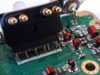
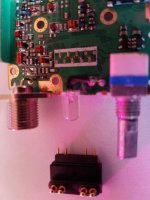
The battery voltage is transferred via spring connections to four pins which push into (very) small sockets soldered to the main pcb.
There appear to be extra sockets on the pcb, probably for other models.
So here is the situation: Ok, getting it apart not too bad. Some of the sockets mounted on the pcb fell off! Now I don't really think I'll find any of these sockets anywhere so I thought I would either: 1) move some of the unused ones, or 2) add short jumper wires between the pins and socket locations.
I really cannot tell exactly where the pins are meant to interface with the pcb! the spacing is such that I really am not sure where I should try to move the sockets to (risky at best - surface mount and tolerance critical) or add jumpers.
I doubt if many people if any have bothered to take one of these apart.
However,
In the event anyone is able to let me know exactly which pcb connection points should be used I would appreciate it.
I have included two pics on this. About the best angle I could get a 'decent' picture of them.
Took the darn thing apart, heck I've wanted to look into one of these for a long time. And it is cheap enough that turning it into a brick won't really hurt.
The battery voltage is transferred via spring connections to four pins which push into (very) small sockets soldered to the main pcb.
There appear to be extra sockets on the pcb, probably for other models.
So here is the situation: Ok, getting it apart not too bad. Some of the sockets mounted on the pcb fell off! Now I don't really think I'll find any of these sockets anywhere so I thought I would either: 1) move some of the unused ones, or 2) add short jumper wires between the pins and socket locations.
I really cannot tell exactly where the pins are meant to interface with the pcb! the spacing is such that I really am not sure where I should try to move the sockets to (risky at best - surface mount and tolerance critical) or add jumpers.
I doubt if many people if any have bothered to take one of these apart.
However,
In the event anyone is able to let me know exactly which pcb connection points should be used I would appreciate it.
I have included two pics on this. About the best angle I could get a 'decent' picture of them.