Bias-T not working with Stridsberg MCA104M HF multicoupler

AOR-262

Member
Joined
May 10, 2016
Messages
317
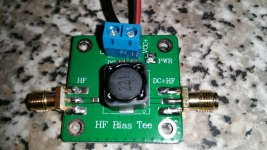
When I connect my Bias-T to the antenna input port and connect the Bias-T to the power supply, the power supply cuts out because of a short. I have tested all connections for continuity and nothing is shorting. On the Bias-T, a short patch cable connects to the input port of the multicoupler (HF+DC) from the Bias-T and the other side of the Bias-T connects to the coax from the MLA-30+ antenna.

Is the Bias-T outputting voltage into the multicoupler that it doesn't like?
 

Attachments

  • 20250115_164632.jpg
    20250115_164632.jpg
    138.2 KB · Views: 20
Last edited:

prcguy

Member
Premium Subscriber
Joined
Jun 30, 2006
Messages
16,706
Location
So Cal - Richardson, TX - Tewksbury, MA
When I connect my Bias-T to the antenna input port and connect the Bias-T to the power supply, the power supply cuts out because of a short. I have tested all connections for continuity and nothing is shorting. On the Bias-T, a short patch cable connects to the input port of the multicoupler (HF+DC) from the Bias-T and the other side of the Bias-T connects to the coax from the MLA-30+ antenna.

Is the Bias-T outputting voltage into the multicoupler that it doesn't like?
There should be no DC on the input side of the bias T. With the bias T only connected to DC power with no coax does it still show a short? I would check solder connections on the bottom side of the bias T as they factory solder looks pretty bad, take for instance one of the ground tabs on the SMA input connector has solder balled up where it didn't flow.
 

AOR-262

Member
Joined
May 10, 2016
Messages
317
@prcguy

Thanks for your reply.

It seems as if my carelessness in connecting the Bias-T the wrong way around was the issue. The Bias-T red LED now lights up ok but none of my receivers receive anything below 30 MHz. This means either I've blown the Bias-T or damaged the multicoupler.

The red LED lights up ok on the multicoupler but I've no way of checking if it's working or damaged. Any suggestions?
 

prcguy

Member
Premium Subscriber
Joined
Jun 30, 2006
Messages
16,706
Location
So Cal - Richardson, TX - Tewksbury, MA
@prcguy

Thanks for your reply.

It seems as if my carelessness in connecting the Bias-T the wrong way around was the issue. The Bias-T red LED now lights up ok but none of my receivers receive anything below 30 MHz. This means either I've blown the Bias-T or damaged the multicoupler.

The red LED lights up ok on the multicoupler but I've no way of checking if it's working or damaged. Any suggestions?
The multicoupler should be protected as no DC should flow that direction from the bias T. Connecting the bias T backwards will put reverse voltage on anything upstream, so you may have cooked the active antenna. Or if your power supply is high enough current and the antenna shorts out with reverse voltage you may have opened the inductor on the bias t. Power up the bias t with nothing connected and see if you can measure any voltage on the antenna side SMA connector. You can install a diode on the bias T to prevent reverse voltage damage in the future.
 

AOR-262

Member
Joined
May 10, 2016
Messages
317
@prcguy

That's reassuring then that the multicoupler is protected from a DC supply going into the input socket - hopefully that is correct and no damage has been done to the multicoupler.

I have ordered a new Bias-T, the exact same one I have here; just in case that is damaged. I can try the new Bias-T when it arrives and hopefully it's only the Bias-T I've damaged. I really have no way to test the multicoupler.

I never thought that possibly by connecting the Bias-T in reverse, DC voltage may have gone through the multicoupler and damaged the circuitry on the loop itself. Although in saying that, I had it so that DC+HF went into the input port of the multicoupler whereas it should of been the other way around. That would mean all my radios would have received DC into their antenna sockets, damaging them all?
 

prcguy

Member
Premium Subscriber
Joined
Jun 30, 2006
Messages
16,706
Location
So Cal - Richardson, TX - Tewksbury, MA
@prcguy

That's reassuring then that the multicoupler is protected from a DC supply going into the input socket - hopefully that is correct and no damage has been done to the multicoupler.

I have ordered a new Bias-T, the exact same one I have here; just in case that is damaged. I can try the new Bias-T when it arrives and hopefully it's only the Bias-T I've damaged. I really have no way to test the multicoupler.

I never thought that possibly by connecting the Bias-T in reverse, DC voltage may have gone through the multicoupler and damaged the circuitry on the loop itself. Although in saying that, I had it so that DC+HF went into the input port of the multicoupler whereas it should of been the other way around. That would mean all my radios would have received DC into their antenna sockets, damaging them all?
I think most radios can withstand some DC on their antenna jacks without any problem.
 

Ubbe

Member
Joined
Sep 8, 2006
Messages
9,808
Location
Stockholm, Sweden
That loops amplifier box runs on +12VDC so if you have that voltage to the bias-T it should work and you can connect a receiver directly to the output of the bias-T to check reception. Then instead connect the Stridsberg to the bias-T output and power also the Stridsberg from 12VDC and if it still works correctly all four outputs should give the same signal reception as you get directly from the bias-T.

The MLA-30+ comes with its own bias-T powered from USB +5VDC and are converted in the bias-T to 12VDC to power the amplifier but are a bit RF noisy from that voltage converter, so that other bias-T you have are preferred to be used when you already have 12VDC.

/Ubbe
 

AOR-262

Member
Joined
May 10, 2016
Messages
317
Apologies guys, this post (my post) is totally wrongly worded from the start.

@prcguy ... when you say the multicoupler should be protected from a DC supply, do you mean internally; such as a diode or other component to prevent voltage going into the multicoupler input OR by the user making sure no DC supply goes into the input?

As a way of an update to my original post ...

Firstly, the two wires (positive and negative) that connect to the Bias-T, there was one single strand (almost invisible to the eye) on the positive that got free and any movement was moving that strand towards the negative - causing my power supply to instantly detect a short and switch itself off.

Secondly, my own lack of attention when connecting the Bias-T to the multicoupler. On the Bias-T, I connected the DC+HF to the input of the multicoupler and the HF to the coax to the loop. That was wrong. It should of been the other way around ... the Bias-T HF output should of been connected to the multicoupler input and the DC+HF to the coax to the loop.

I've reconnected my original MLA-30+ Bias-T to the antenna and also to one of my receivers and it works ok. However if I use that or the other Bias-T I've got and connect them to the multicoupler as it should connect, I get nothing from any of the 4 output ports. Clearly I've blown the multicoupler. So guys, my carelessness of connecting the Bias-T the wrong way was one costly mistake!

Thanks @prcguy and @Ubbe for your replies. Much obliged to you all.
 

prcguy

Member
Premium Subscriber
Joined
Jun 30, 2006
Messages
16,706
Location
So Cal - Richardson, TX - Tewksbury, MA
Apologies guys, this post (my post) is totally wrongly worded from the start.

@prcguy ... when you say the multicoupler should be protected from a DC supply, do you mean internally; such as a diode or other component to prevent voltage going into the multicoupler input OR by the user making sure no DC supply goes into the input?

In that case I meant the multicoupler should be automatically protected because the bias T will not output voltage on the radio side. If you accidently connect the bias T backward then you will feed voltage into the multicoupler and that can draw current through balancing resistors inside the power divider.
 

Ubbe

Member
Joined
Sep 8, 2006
Messages
9,808
Location
Stockholm, Sweden
As it is a multicoupler for HF signals it could have a coil to ground at its input as a low pass filter and to bleed off any static voltage from an antenna connected to it. That coil are probably a surface mount type that can only handle a small current. But if it blows up it will not shortcircuit but instead go open circuit and can be part of a DC voltage level to its amplifier transistor that stops working due to wrong operational voltage.

Only thing to check are to disconnect the coax to its input and listen with a receiver that you actually have a signal to it and then check if its power led are lit, indicating that its fuse are good. If you can solder you can open it up and look at the components at the antenna input if any looks to be burnt.

/Ubbe
 
Top