• To anyone looking to acquire commercial radio programming software:

    Please do not make requests for copies of radio programming software which is sold (or was sold) by the manufacturer for any monetary value. All requests will be deleted and a forum infraction issued. Making a request such as this is attempting to engage in software piracy and this forum cannot be involved or associated with this activity. The same goes for any private transaction via Private Message. Even if you attempt to engage in this activity in PM's we will still enforce the forum rules. Your PM's are not private and the administration has the right to read them if there's a hint to criminal activity.

    If you are having trouble legally obtaining software please state so. We do not want any hurt feelings when your vague post is mistaken for a free request. It is YOUR responsibility to properly word your request.

    To obtain Motorola software see the Sticky in the Motorola forum.

    The various other vendors often permit their dealers to sell the software online (i.e., Kenwood). Please use Google or some other search engine to find a dealer that sells the software. Typically each series or individual radio requires its own software package. Often the Kenwood software is less than $100 so don't be a cheapskate; just purchase it.

    For M/A Com/Harris/GE, etc: there are two software packages that program all current and past radios. One package is for conventional programming and the other for trunked programming. The trunked package is in upwards of $2,500. The conventional package is more reasonable though is still several hundred dollars. The benefit is you do not need multiple versions for each radio (unlike Motorola).

    This is a large and very visible forum. We cannot jeopardize the ability to provide the RadioReference services by allowing this activity to occur. Please respect this.

Dipole feed line length question

Status
Not open for further replies.

brizzotheizzo

Member
Joined
Aug 7, 2016
Messages
53
I guess I went old school ... I had to add some electrical wire to get it to resonate on ch 38 CB and added some weed whacker string on the ends to stop the pvc elements from sagging in the sun . No analyzer just got the SWR low and talked to some guys in my city then talked to a base station 15 miles away so i figured its working....Went on 10 Meters and talked to the local net on 28.490 with the HTX-10 when the DX opened
up I talked to Carolina and Tenn so I figure its working. As for the trap I read it on line to make 21 turns..I figure it works or it does not do a thing
and the coffee container was what i had.... Don't let it get you down about experimenting ... I know I broke allot of rules but I got it to work.

Mine is in the back yard off the grape vine pipes....No way would I put it on the roof... Too High and it would look pretty Ugly... !

Peter N1EXA
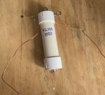
Hey, if you’re talking on it, Mission accomplished. My father always taught me “hustling” is doing the best with what you got. I guess that makes me a “hustler” when it comes to this stuff. And like you said, if it works...great...if not, keep trying until it does. And the bonus is that we usually get a free education in the process. Maybe not always the “easy way“ but an education none the less.

My dad used to always say, if it wasn’t for hustling, and learning through failure, the Wright brothers would’ve never invented the airplane.
 

brizzotheizzo

Member
Joined
Aug 7, 2016
Messages
53
So I’m trying to build a dipole antenna. I’m torn between a horizontal or a inverted V Dipole. It will be for 11 meters. I talk to local traffic here in town, and I love to talk side band skip when it is rolling through. This is what is leading me to confusion between an inverted v dipole (better for local comms) vs a horizontal dipole (better for skip).
I have seen “fan dipoles” and the MFJ “octopus “ dipole for a Multi bandwidth antenna using the same feedline. But would it be possible to mix an inverted V antenna and horizontal dipole together for good local And dx skip talk? Or is this a train wreck waiting to happen. Both dipoles would both be tuned to the 11 m band, but would be directly opposed and positioned opposite of each other. I don’t have access to EZNEC or any other antenna design software. And this is very hard to draw as it is very three-dimensional. I have included a photo below using bread ties as the antennas and a paper clip as a feedline Give the crudity of this model, but I am trying to express this idea the best way I know how.21A2BFE1-F99F-4CDB-81BA-DB1BC10D95CA.jpeg
The green bread tie is the horizontal dipole, and the brown bread tie is the inverted V. Both fed off the same feed line.

Am I being ignorant, or could this work? I know I would be sacrificing something, as energy doesn’t come from nothing. Does anyone with access to antenna modeling software have the ability to program this model and post the results? The antenna feedpoint will be five eights of a wavelength high.(About 25 feet).4 watts power. Feedline length is 30ft. There will be a 1:1 Current balun/choke at the antenna feedpoint. Antenna will be tuned to 27.205mhz. Both antennas will be 1/2 wavelength. And the inverted v elements will be at 90 degrees opposed. Fed with RG-58 coax direct from radio.
 

prcguy

Member
Joined
Jun 30, 2006
Messages
15,325
Location
So Cal - Richardson, TX - Tewksbury, MA
An inverted V with a 90 deg angle or elements at 45 deg to vertical or horizontal will have slant polarization broadside and sort of vertical pol off the ends and it will be somewhat omni directional. For talking to locals on vertical antennas you may see up to a 3dB degradation due to the 45 deg slant polarity. If you add another dipole, power will be divided to each dipole as one problem and each will receive about half power and radiate half as much as one receiving full power. The other problem is you will pull the feed point impedance down below 50 ohms and closer to 25 ohms if each individual dipole is close to 50 ohms.

There are ways to combine two 50 ohm antennas and provide a good 50 ohm match to both antennas and the radio using a Wilkinson power divider but each antenna will still see half power and radiate half as much. No free lunch here.

Skip signals are random polarity and constantly changing. There is a slight advantage with a horizontal antenna in picking up less noise and you can rotate the antenna to null out noise sources but you would not do well horizontal talking to locals with vertical antennas. I don't see any advantage transmitting horizontal for skip except you can rotate the antenna and cause less interference to someone else, not that anyone cares.

The inverted V is ok for skip because its splitting the difference between horizontal and vertical and may even have slightly less fading on skip signals as they change polarity. If you go vertical you can give the locals everything you got plus it will transmit back to distant skip stations fine but it might be slightly noisier than horizontal on receiver. Pick your poison.
 

wowologist

Certifiable
Joined
Jul 21, 2013
Messages
275
Location
CM87
You also have to remember we're at the literal bottom of the solar cycle, 4 watts or 11 SSB isnt really going to get you much these days. Another 6 years or so you may be getting some skip. As far as cheapo depot...get a mag mount k40 or similar and put it on a cookie sheet and have some fun.
 

brizzotheizzo

Member
Joined
Aug 7, 2016
Messages
53
So, as far as the solar cycles I’ve been talking to Canada a lot lately from the Midwest USA, so it hasn’t been too horrible. And that’s for 4 W out of a mobile with a fire stick antenna on side band! Even though the solar cycles have been down, I’ve been getting some good Skip lately. As far as the antenna, thanks for all the advice above, I think I’m gonna go with the Single, “slightly“ inverted V, and tune it to impedence match. and yes you all are right, no free pie in the power area!
Even if I don’t get good Skip with the inverted V, I know mom mobile is dependable and good for it. Just trying to get my “best of both worlds” in the end in the area, and I am Abruptly reminded that there is no such thing. Lol
 

brizzotheizzo

Member
Joined
Aug 7, 2016
Messages
53
When measuring for dipole antenna wire length, do I include the extra 10 inch of feedline wire from my balun? Or no?
 

Attachments

  • AACC7735-D704-4C34-813A-C263DEE0FE5F.jpeg
    AACC7735-D704-4C34-813A-C263DEE0FE5F.jpeg
    126.4 KB · Views: 12

KEWB-N1EXA

Acushnet Heights Radio 740
Joined
Jan 1, 2020
Messages
416
234/frequency X 12= length in inches.

It all counts so add it in. Had to do it to my antenna !

Then had to add 2 more inches just to get the swr down for ch 38.

234/27.125 x 12 = 103.5 inches

Peter N1EXA
 

brizzotheizzo

Member
Joined
Aug 7, 2016
Messages
53
Well, just got it all soldered up. I left about an extra foot on both sides of the wire just to have some “wiggle room“. Going to hang it tomorrow and Tune it up. Got a feeling I’ll be trimming a little bit off both ends. Had to stop for today. The wife was giving me the ...you’re playing with your radio stuff too much face“. :ROFLMAO:Time to mow the yard before the rain comes.
 

KEWB-N1EXA

Acushnet Heights Radio 740
Joined
Jan 1, 2020
Messages
416
Well, just got it all soldered up. I left about an extra foot on both sides of the wire just to have some “wiggle room“. Going to hang it tomorrow and Tune it up. Got a feeling I’ll be trimming a little bit off both ends. Had to stop for today. The wife was giving me the ...you’re playing with your radio stuff too much face“. :ROFLMAO:Time to mow the yard before the rain comes.

Happy Wife Happy Life !
 

ko6jw_2

Member
Premium Subscriber
Joined
May 18, 2008
Messages
1,448
Location
Santa Ynez, CA
Just remember that antenna formulas are a good starting point. If you are transmitting you will need to adjust the length for the lowest SWR. For receiving it won't make that much difference. Unless you have an antenna analyzer just use the formula for receive only.
 

brizzotheizzo

Member
Joined
Aug 7, 2016
Messages
53
Just remember that antenna formulas are a good starting point. If you are transmitting you will need to adjust the length for the lowest SWR. For receiving it won't make that much difference. Unless you have an antenna analyzer just use the formula for receive only.
Yes , I am aware. I just couldn’t even measure a good “starting point “ because I had 20 inches of feedline wire that I didn’t know if I was supposed to count in the measurement or not.
 

ko6jw_2

Member
Premium Subscriber
Joined
May 18, 2008
Messages
1,448
Location
Santa Ynez, CA
Not quite sure why the wires are sticking out under the cap on the balun. They should connect to the eyelets on each side and the eyelet on the top is to hang the balun.
 

brizzotheizzo

Member
Joined
Aug 7, 2016
Messages
53
Not quite sure why the wires are sticking out under the cap on the balun. They should connect to the eyelets on each side and the eyelet on the top is to hang the balun.


that’s the way they come from MFJ.

I used the process shown at 17:30 in this video.

My understanding was that it did not matter if they were hooked to the eyelits or not, due to the fact that the eyelits were for hanging/tension purposes only. Just as long as there was not tension on the line at the contact point.


4F4A8466-A235-43C6-B245-0DD9A973DB84.jpeg
 
Last edited:

Ubbe

Member
Joined
Sep 8, 2006
Messages
9,028
Location
Stockholm, Sweden
Dipole types of antennas are always measured tip to tip and it does not matter how wide the gap are where they meet in the middle. It is radio waves you receive or transmit that should match the ends of the dipole in a matematical relation and then you have the delay constant in the material of the antenna to consider that makes the antenna slightly shorter.

/Ubbe
 
Status
Not open for further replies.
Top