
Ubbe
Member
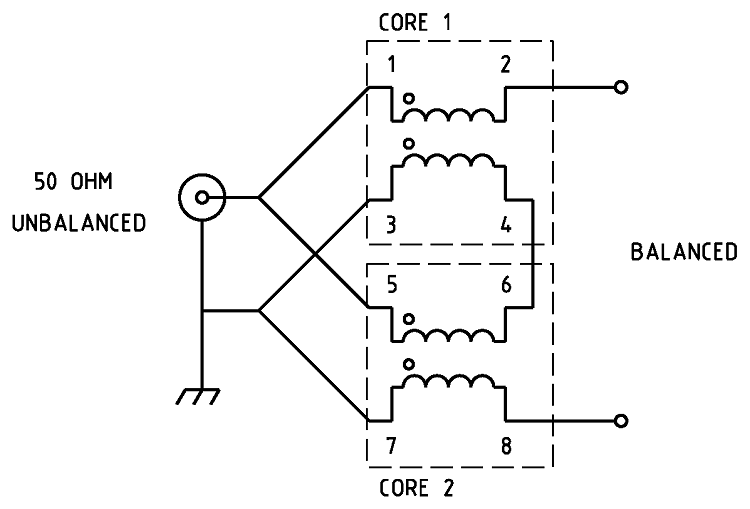
I found the page for that that 1:4 guanella dual core balun. Balun Guanella Current 1:4
The schematic can be found on many other pages and some refer to pin 2 as "hot" and pin 8 as "cold".
When a dipole are tuned and in resonance if will have an impedance lower than 100 ohm. When it's out of tune and not resonant if will have several hundred or even thousands of ohm. A 1:4 balun used at the resonant frequency will just reduce the received signal 4 times but out of tune frequencies will work with a better match so it will create a more broadbanded antenna by sacrificing performance at the resonant frequencies.
A OFCD antenna will have one leg in resonance at low impedance and the other leg more or less as a passive element at a higher impedance and will begin to work more like a single element antenna with a counterpose depending of how much offset are used.
/Ubbe
