Discriminator tap on BC700

Status
Not open for further replies.

kadetklapp

Member
Joined
Jun 1, 2007
Messages
328
Location
Indiana
Performed Google-foo and a search here. I need an illistration of the pinout on discriminator tapping a BC700 analog scanner. Any hints or tips?
 

kadetklapp

Member
Joined
Jun 1, 2007
Messages
328
Location
Indiana
Found an old thread from 2006-
http://forums.radioreference.com/pr...pco-data-older-scanner-discriminator-tap.html

In the picture below you'll see where I've outlined chip 3359D-A on circuit IC-3. Past that, I'm completely lost. Not sure what I need to tap onto. If someone could throw me a bone here, that would be great.
discriminator.jpg
 

kadetklapp

Member
Joined
Jun 1, 2007
Messages
328
Location
Indiana
Thanks Mike.

I've never performed a mod on any radio before, so this is a little bit out of my realm. I know I want pin ten but I don't know which one is pin ten, as they are not identified on the board.
 

ka3jjz

Wiki Admin Emeritus
Joined
Jul 22, 2002
Messages
25,387
Location
Bowie, Md.
There's a way to make an educated guess as to which pin is 10 - it's documented at the bottom of the first link. Following those directions (the pic resolves very fuzzy on my laptop), I would say the rightmost pin on the top row is 10.

If this doesn't fly, I wonder if you can google the chip number and get something to show you the pin configuration 73 Mike
 
Last edited:

kadetklapp

Member
Joined
Jun 1, 2007
Messages
328
Location
Indiana
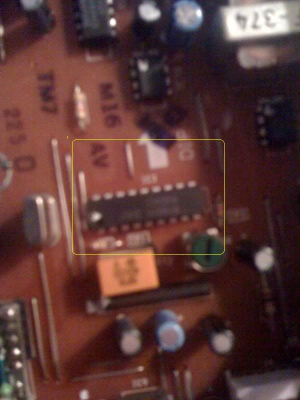
Sorry the picture resolution is terrible. There are 9 pins on each side of the black chip labeled 3359da. Is each leg coming out of this black chip considered to be a "pin?"

**ETA**

Ok, looking at the diagram at the first link, I've been able to deduce which side is "up" on the chip, notch/dot etc. However, the chip in the illustration has 8 pins on each side as mine has 9.

If I took a chance and tapped the top right pin as pin ten, what is the best physical method to do this? Soldier on the chip side or flip it over and do it on the board side? Again, I've never done any work like this before.
 
Last edited:

ka3jjz

Wiki Admin Emeritus
Joined
Jul 22, 2002
Messages
25,387
Location
Bowie, Md.
I would likely do this on the board side. You will also need to find the ground trace to solder the braid for the connecting cable. Once the operation has been successfully tested, wrap the leads in shrink wrap to prevent accidental shorts. Follow the directions as shown in part 3. Keep in mind that the diagram in part 2 was only there to demonstrate how to count the pins correctly - 10, 9 or 13 pin ICs would be all read the same way, barring having the actual diagram for the IC handy.

If what I just said is unfamiliar, time to talk to someone about actually doing the mod. G&G and DataSlicers are two possibilities - their links are in a section called 'companies known to do modifications' in..

Category:Modifications - The RadioReference Wiki

73 Mike
 

kadetklapp

Member
Joined
Jun 1, 2007
Messages
328
Location
Indiana
Thread of Olde, arise from thy grave.

Finally got around to finishing this up. DiGiTaL D came by and cleaned up my soldering work and we added some longer cord. It's happily working away on my desktop. If I improve the antenna location I'll be happier, but for now I'm amazed at this software. The BC700 makes a pretty good tap radio, IMO.
 
Status
Not open for further replies.
Top