DIY - Modifying Discone Antenna Dimensions: Impact on Reception?

wagros

Member
Premium Subscriber
Joined
Nov 23, 2022
Messages
40
Location
Sao Paulo, SP, Brasil
Hello, friends.

I’m looking to build a portable discone antenna, but some of the dimensions I got from the discone calculator are making the project a bit challenging. I’d like to ask the forum experts, as I’m just a beginner, which variables I can change without compromising its reception. I emphasized the word "reception" because my intent is to use it solely for radio listening in the 118 MHz to 470 MHz range, occasionally reaching up to around 900 MHz.

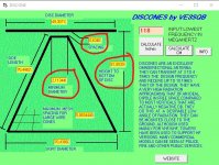
Considering the image below, it would be helpful to have the freedom to alter the two circled dimensions. Do you think this change might reduce the antenna's performance?
discone_forum.jpg
 

pro92b

Mutated Member
Premium Subscriber
Joined
Jun 27, 2002
Messages
1,947
Considering the image below, it would be helpful to have the freedom to alter the two circled dimensions.

You circled three dimensions. The spacing and minimum diameter dimensions degrade the upper end of the frequency coverage if they get too large. A discone with 118 MHz lower limit will not perform well at 900MHz in any case. If you only want reception of fairly strong 900 MHz signals it will be adequate. Reducing height to bottom of disc will also necessarily reduce side length and skirt diameter. Doing this will move the lower cut-off frequency upwards from 118 MHz.
 

wagros

Member
Premium Subscriber
Joined
Nov 23, 2022
Messages
40
Location
Sao Paulo, SP, Brasil
Actually, most of my listening is between 150 and 180 MHz, and 370 to 470 MHz. A bonus would be the aviation band, and very rarely close to 900 MHz. Therefore, I can disregard the higher frequencies if I can increase the minimum diameter and spacing.
 

prcguy

Member
Premium Subscriber
Joined
Jun 30, 2006
Messages
16,184
Location
So Cal - Richardson, TX - Tewksbury, MA
A Discone is a non resonant antenna related to a horn or V beam antenna where a wave is launched from the apex of the disc and cone. The longer cone elements determine the low frequeny cutoff and are close to 1/4 wavelength at the lowest design frequency. The top disc is calculated around .67 to .7 the length of the cone elements. The spacing between the disc and cone will vary the impedance. This is the original specs from the 1940s which had about an 8:1 frequency range and not much has changed since then except some narrower band versions have been made and newer scanner versions put a resonant whip on top, which is not the best idea.

Your 118 to 900MHz frequency range fits within the 8:1 range of a discone but that is more for providing a good match and a discone has a problem of the main lobe starting to point upward above the horizon about half way through its frequency range. So a 118 to 944MHz discone will point up high above the horizon at 900MHz and you will loose gain and I have measured about a 10dB loss, so discones are not the best choice for covering an 8:1 frequency range unless you can live with poor performance at the upper frequency ranges.

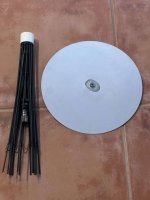
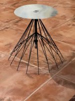
There is no good way to reduce the size of a discone without loosing performance or affecting the VSWR. You might be able to shorten the cone elements by using helically wound wire around an insulated rod where the resonant frequency is still the same as a full size cone element. The minimum diameter for the top of the cone is probably most sensitive at the higher frequencies and if a little wider should not affect the lower frequencies that much. Otherwise I don't have any good advice on how to reduce the size of a discone. I also think a discone would be one of the more difficult antennas to make into a portable. I have a couple of portable military discones and they are not fun to assemble in the field. Ok, except for maybe one in the picture below. Its was made in about 1950 and its very well made. Its spring loaded and collapses into a tube for storage. It would be very difficult and expensive to duplicate. This one was designed for the 200-400MHz range and I had to make a new top disc for it.

IMG_9286.jpgIMG_9287.jpg
 

wagros

Member
Premium Subscriber
Joined
Nov 23, 2022
Messages
40
Location
Sao Paulo, SP, Brasil
A Discone is a non resonant antenna related to a horn or V beam antenna where a wave is launched from the apex of the disc and cone. The longer cone elements determine the low frequeny cutoff and are close to 1/4 wavelength at the lowest design frequency. The top disc is calculated around .67 to .7 the length of the cone elements. The spacing between the disc and cone will vary the impedance. This is the original specs from the 1940s which had about an 8:1 frequency range and not much has changed since then except some narrower band versions have been made and newer scanner versions put a resonant whip on top, which is not the best idea.

Your 118 to 900MHz frequency range fits within the 8:1 range of a discone but that is more for providing a good match and a discone has a problem of the main lobe starting to point upward above the horizon about half way through its frequency range. So a 118 to 944MHz discone will point up high above the horizon at 900MHz and you will loose gain and I have measured about a 10dB loss, so discones are not the best choice for covering an 8:1 frequency range unless you can live with poor performance at the upper frequency ranges.

There is no good way to reduce the size of a discone without loosing performance or affecting the VSWR. You might be able to shorten the cone elements by using helically wound wire around an insulated rod where the resonant frequency is still the same as a full size cone element. The minimum diameter for the top of the cone is probably most sensitive at the higher frequencies and if a little wider should not affect the lower frequencies that much. Otherwise I don't have any good advice on how to reduce the size of a discone. I also think a discone would be one of the more difficult antennas to make into a portable. I have a couple of portable military discones and they are not fun to assemble in the field. Ok, except for maybe one in the picture below. Its was made in about 1950 and its very well made. Its spring loaded and collapses into a tube for storage. It would be very difficult and expensive to duplicate. This one was designed for the 200-400MHz range and I had to make a new top disc for it.

View attachment 167906View attachment 167907
Wow, that’s a very interesting discone you have!
I’ll try to be a bit clearer.
I want to increase the diameter of the smaller disc because, for my construction idea to succeed, it would ideally need to be about 50 mm in diameter, not 21.1 mm as calculated. Also, the distance between the discs should be at least 15 mm.
All this without causing issues in the frequencies I mentioned earlier: "between 150 and 180 MHz, and 370 to 470 MHz. A bonus would be the aviation band."
 

Ubbe

Member
Joined
Sep 8, 2006
Messages
9,586
Location
Stockholm, Sweden
The spacing between upper and lower elements will be too large at higher frequencies and the impedance run away and makes the antenna perform worse and its directions pattern changes.

The lower elements are a 1/4 wave seen from the side, x0.96 for account for the delay in the material.
The upper element are 1/4 wave for the middle of the frequency range, usually 300MHz as it is in this case. The SWR are supposed to be acceptable 3 multiples down and up in frequency, 100MHz and 900MHz but as mentioned the upper range above 600MHz will be compromised.

The mesh spacing will also be the distance between the lower elements at its highest frequency. The lower you go in frequency the larger the radio wave will be and the spacing can be wider at the lowest part of the skirt elements. Something like 8 skirt elements are the minimum but most discones for home use use 6. Some military discones can have 16 elements.

Trying to shorten the lower skirt elements by using coils will not work. They are used if the discone has a vertical top element tuned to a lower frequency below what the discone handles to have the whole antenna instead work as a 1/4 wave GP.

/Ubbe
 

merlin

Active Member
Joined
Jul 3, 2003
Messages
3,083
Location
DN32su
Nothing I can add to prcguy's post. Best bet is leave 'as is'. Broadband range is about 110 MHz to 950 MHz.
Increasing the diameter of the small disc will lean toward cutting off your lower frequency (air band)
 
Top