e-probe vs. vertical

below500kc

Member
Joined
Nov 19, 2019
Messages
22
As I have made and used both e-probe and vertical antennas, I've been contemplating a situation that I'd like to get some "feedback" on. Ok, here's the way I'm looking at the comparison between the two types of antennas. First, let's try and make it a fair and equal "shootout".

So let's imagine an e-probe and vertical setup like this:
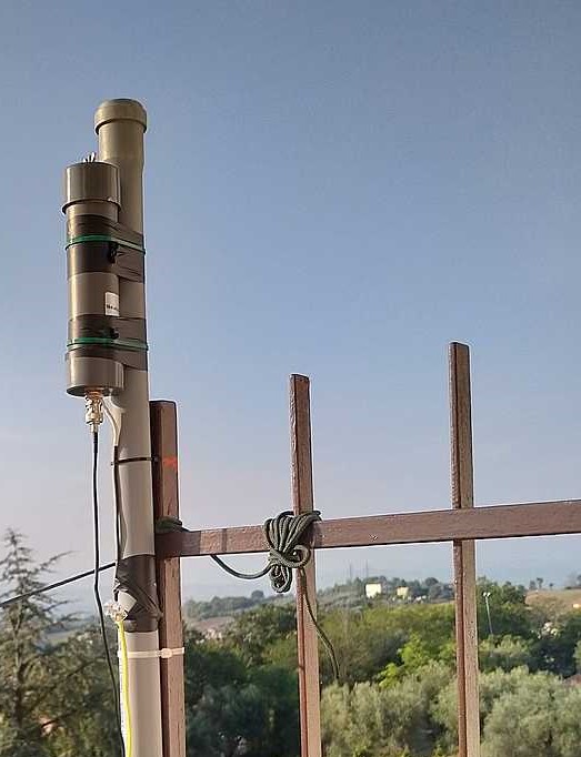
The e-probe:
Sitting on top of a conductive 20ft. mast
Underneath the mast is a shallow buried radial system... 6 wire radials 20 ft. long with a wire circularly connecting all of them together at the far end. Mast connected to radial system.
The "ground" of the e-probe directly connected to the conductive mast. The coax running up along the mast must pass through a common mode choke at the e-probe base before connecting to same.
100ft of coax running along the ground/earth into the shack to meet the bias-tee and receiver.
This system will need to perform decently between 100khz and 30 mhz.

The vertical:
A 20ft. conductive mast with the same ground system as the e-probe, insulated at the base from that ground system.
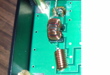
An impedance step-up auto-transformer made from an appropriate low freq material that will allow non-resonant broadband rx from 100khz to 30 mhz. Let's give it, for example, a 49:1 turns ratio.
The transformers primary will be placed across the coax at the base of the mast and grounded to the wire system. The one secondary wire will tie to the mast vertical.
Same run of coax to the shack to the receiver minus the bias-tee.

Ok, with that out of the way, here's where I'm going with this...

It's my belief that there is really no advantage to using an e-probe over the simple vertical. You would also have a small increase in noise level using the e-probe over the vertical since there will always be a small amount of noise generated by the amplification in the probe. If the probe is not well designed, you also run the risk of intermodulation if in a relatively dense RF surrounding with AMBCB stations. Of course, you also have to expend a small amount of dc power to run the probe.

You may say that the vertical may perform poorly at 30mhz due to the loss of 100 ft. of coax. However, if the receiver at the other end "notices" an increase in noise level when the coax is connected, the level of snr will be adequate for reception with that receiver.

I use both antenna types, but I feel that there's no advantage to an e-probe when used as above. I think an e-probe would "shine" if it were used on a metal surface such as a roof used as the counterpoise.

Any thoughts on this comparison would be welcomed... pro or con.

Ray
 

ka3jjz

Wiki Admin Emeritus
Joined
Jul 22, 2002
Messages
25,560
Location
Bowie, Md.
Your idea about using an e probe antenna over a counterpoise is a good one. See this article linked in our wiki from SWLing.com


Personally if I had a choice between an e probe antenna (as described above) and a loop, the loop has it hands down if you are fighting condo nazis or a HOA. But that's just me....

Mike
 

below500kc

Member
Joined
Nov 19, 2019
Messages
22
Your idea about using an e probe antenna over a counterpoise is a good one. See this article linked in our wiki from SWLing.com


Personally if I had a choice between an e probe antenna (as described above) and a loop, the loop has it hands down if you are fighting condo nazis or a HOA. But that's just me....

Mike
Hi Mike. Yep, the counterpoise/coaxial common mode choke idea works to keep the feed coax from becoming part of the antenna. That was an interesting article the link pointed to. The idea of running the coax horizontally away from the e-probe was unusual, may help, but in some installations (like mine) not practical to impliment.

I could stealth/conceal either e-probe or vertical if I had to. I'm not sure a loop would deliver any better snr than the other two, unless there is a noise issue to be dealt with. I'm assuming that the loop would be operated in broadband fashion like the other two antennas. That's just my own conclusion, and not necessarily the last word on the subject.
 

ka3jjz

Wiki Admin Emeritus
Joined
Jul 22, 2002
Messages
25,560
Location
Bowie, Md.
Loops by their very nature would have a lower noise figure (dependent on the amp design, of course) then either a vertical or an e field antenna. You would not need a lot of work to get a good ground / counterpoise as you would with both of these antennas. One thing that is a great benefit to folks looking to hide the antenna is that loops (like the W6LVP, MFJ, etc.) work just fine close to the ground. This allows them to be directional on frequencies below 2 Mhz or so (dependent on the loop design). Mount them too high and you lose that directionality. This is great for MW and LW folks who sometimes need to null one station over another. Even on HF you may be able to turn the loop away from a noise source, something neither an e field nor a vertical is capable of

Mike
 
Last edited:

prcguy

Member
Premium Subscriber
Joined
Jun 30, 2006
Messages
15,990
Location
So Cal - Richardson, TX - Tewksbury, MA
I think a 49:1or higher ratio is good for a 6ft vertical but not a 20ft, which is a 1/4 wave and low impedance at 11.7mhz. For coverage 100KHz through 30MHz I would recommend a 6ft whip and 100:1 transformer or if you go longer consider limiting the top end frequency.
 

below500kc

Member
Joined
Nov 19, 2019
Messages
22
Loops by their very nature would have a lower noise figure (dependent on the amp design, of course) then either a vertical or an e field antenna. You would not need a lot of work to get a good ground / counterpoise as you would with both of these antennas. One thing that is a great benefit to folks looking to hide the antenna is that loops (like the W6LVP, MFJ, etc.) work just fine close to the ground. This allows them to be directional on frequencies below 2 Mhz or so (dependent on the loop design). Mount them too high and you lose that directionality. This is great for MW and LW folks who sometimes need to null one station over another. Even on HF you may be able to turn the loop away from a noise source, something neither an e field nor a vertical is capable of

Mike
Mike, I'm still not convinced the loop would deliver a better snr over the lf-hf range than the other two as long as the man-made noise level at a location wasn't a factor. Perhaps I should just give it a try and see if you're right. I have a loop and a good amp schematic I'd been wanting to put to use. Thanks for your advice.
 

below500kc

Member
Joined
Nov 19, 2019
Messages
22
I think a 49:1or higher ratio is good for a 6ft vertical but not a 20ft, which is a 1/4 wave and low impedance at 11.7mhz. For coverage 100KHz through 30MHz I would recommend a 6ft whip and 100:1 transformer or if you go longer consider limiting the top end frequency.
prcguy... yea, I was just sort of running with the ratio I normally use to optimize the vertical for the lower freqs. You're right, a 49:1 would compromise the upper end of the HF range.
 

prcguy

Member
Premium Subscriber
Joined
Jun 30, 2006
Messages
15,990
Location
So Cal - Richardson, TX - Tewksbury, MA
prcguy... yea, I was just sort of running with the ratio I normally use to optimize the vertical for the lower freqs. You're right, a 49:1 would compromise the upper end of the HF range.
I think it’s more about a 20ft vertical compromising the high freqs. When a whip is really small like sub fractions of a wavelength throughout it’s entire frequency range, it can present a fairly constant and very high impedance at the feedpoint where a 100:1 transformer might be a good choice.

For 100KHz or lower through 30MHz the whip is often 1m long to stay within the desired impedance range. Go to 6ft and the low end perks up but at 30MHz you’re getting close to 1/4 wavelength, low impedance and a bad match to a 100:1 transformer. That’s why most VLF through 30MHz E-field probes have 3ft or less whips to keep a constant high impedance load on the input amplifier.

You could use a 20ft vertical and a 100:1 transformer for VLF into maybe medium wave but I think it would be getting too long by the time you reach 80m. But that should work really well 30KHz through about 2MHz.
 

below500kc

Member
Joined
Nov 19, 2019
Messages
22
I think it’s more about a 20ft vertical compromising the high freqs. When a whip is really small like sub fractions of a wavelength throughout it’s entire frequency range, it can present a fairly constant and very high impedance at the feedpoint where a 100:1 transformer might be a good choice.

For 100KHz or lower through 30MHz the whip is often 1m long to stay within the desired impedance range. Go to 6ft and the low end perks up but at 30MHz you’re getting close to 1/4 wavelength, low impedance and a bad match to a 100:1 transformer. That’s why most VLF through 30MHz E-field probes have 3ft or less whips to keep a constant high impedance load on the input amplifier.

You could use a 20ft vertical and a 100:1 transformer for VLF into maybe medium wave but I think it would be getting too long by the time you reach 80m. But that should work really well 30KHz through about 2MHz.
Your ratios and lengths sound fine for both the short whips and the 20 ft. vertical. I appreciate your suggestions, thanks. On the higher hf freqs with the longer vertical, what I've been using has not been optimum impedance-wise, but I've operated on the premise that as long as enough signal is "gathered" to be roughly a few db or so above the receivers noise floor, then any further increase in signal by attempting a better match (or amplification) will not improve the snr. Of course, one undoubtably will run into a situation somewhere on upper hf where the vertical winds up being 3/4 wave or so making the antenna rather insensitive to the lower angle dx.
 

db_gain

Member
Joined
Sep 13, 2014
Messages
112
At issue with the e probe and active verticals in general is that pole/mast employed in support is often bonded to the e probe ground, meaning the e probe sees a far greater rf input than the typical 4 square centimeter or even 1m long stinger would deliver by itself. And then there's the coax, wich will also add its rf picked up to the e probe amp. All that takes place unless one uses a liberal amount of ferrets I mean ferrites on the feedlines and decouples the e probe from the mast. Then you will see what good a 4cm square patch or 1m long wire is as a wideband antenna. A simple vertical, 6 to 20ft in length, will likely be of similar performance to a grounded e probe in the same location and height.
 

netosilva

Member
Joined
May 26, 2023
Messages
8
descobri o segredo de como funciona o balun (bobina de acoplamento), fiz um balun e conectei na minha antena de 1,60m, funcionou perfeitamente de 100 KHz a 30 MHz. o segredo está no balun dentro da antena.
veja o balun, primário (ligado à antena e terra) 4 grupos de 8 voltas, secundário 4 voltas (ligado ao capacitor da antena 470nf e terra), a cada 8 voltas do primário 1 volta do secundário. totalizando 32 espiras primárias e 4 espiras secundárias. na foto abaixo balun da antena AOR SA7000, mesmo tamanho da ApexRadio 303WA-2, 1,80m.
 

Attachments

  • Sem título.png
    Sem título.png
    763.8 KB · Views: 2

netosilva

Member
Joined
May 26, 2023
Messages
8
descobri o segredo de como funciona o balun (bobina de acoplamento), fiz um balun e conectei na minha antena de 1,60m, funcionou perfeitamente de 100 KHz a 30 MHz. o segredo está no balun dentro da antena.
veja o balun, primário (ligado à antena e terra) 4 grupos de 8 voltas, secundário 4 voltas (ligado ao capacitor da antena 470nf e terra), a cada 8 voltas do primário 1 volta do secundário. totalizando 32 espiras primárias e 4 espiras secundárias. na foto abaixo balun da antena AOR SA7000, mesmo tamanho da ApexRadio 303WA-2, 1,80m.
the secret of the apexradio 303wa-2 and SA 70000 antenna is in the balun (coupling coil), I made a balun and connected it to my 1.60m antenna, it worked perfectly from 100 KHz to 30 MHz. the secret is in the balun inside the antenna.
see the balun, primary (connected to the antenna and ground) 4 groups of 8 turns, secondary 4 turns (connected to the 470nf antenna capacitor for the RX and ground), every 8 turns of the primary 1 turn of the secondary. totaling 32 primary turns and 4 secondary turns. I'm doing tests on a 1.50m antenna.
 
Top