External Lowpass Filter for UniTrunker design thread

Status
Not open for further replies.

jcardani

Member
Premium Subscriber
Joined
Jan 16, 2002
Messages
1,390
Location
Orlando, FL & Ocean City, NJ
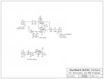
New Simplified Design

I simplified the original circuit eliminating the low pass filter for LTR since it can be implemented in software.

Do you think this circuit can be of help to those with problems with their scanner's discriminator output?

Suggestions, comments, and corrections are encouraged!

thank you,
 

Attachments

  • 2014 Soundcard Buffer1.jpg
    2014 Soundcard Buffer1.jpg
    25.3 KB · Views: 132

SCPD

QRT
Joined
Feb 24, 2001
Messages
0
Location
Virginia
Thanks Joe.

I've had no problems using a simple potentiometer for isolation and level adjustment.

Nowadays, I think most folks are better off buying an RTL stick.
 

jcardani

Member
Premium Subscriber
Joined
Jan 16, 2002
Messages
1,390
Location
Orlando, FL & Ocean City, NJ
Hi RIck,

Does the buffer circuit help at all with the signal and do the other components after the opamp help filter the crud out of the discriminator output?

Been so long ago I forget why the non LTR filtered circuit was designed this way.

thanks,
joe
 

SCPD

QRT
Joined
Feb 24, 2001
Messages
0
Location
Virginia
Sigh.

Let's go back four years:

unitrunker said:
I will try this out. If I understand right, this is computationally equivalent to a 64 tap FIR filter at 3k sps. That's under 200k multiply accumulate operations per second compared to 1 to 3 million "macs" per second for a direct FIR at the primary sample rate.

The conclusion from the whole discussion thread was a software solution rather than a hardware solution.

unitrunker said:
I'll let everyone know once I've got it working.

Related improvements to Unitrunker appeared the following month with version 1.0.0.14.

Release 14

LTR decoding from discriminator audio was a bust but it did eventually result in much better weak signal decoding for the other protocols.

In summary, this whole thread is pretty much obsolete.
 

jcardani

Member
Premium Subscriber
Joined
Jan 16, 2002
Messages
1,390
Location
Orlando, FL & Ocean City, NJ
Hi Rick,

I was referring to the unfiltered path in the circuit, not the LTR low pass filtered path. I know that the low pass filtering is much easier done with software. In fact didn't you help me with that a few years back.

I was wondering why the entire circuit was designed with a input buffer opamp and the 10 ohm resistor and 10uf cap after the opamp. I thought the later 2 was due to better sound card interfacing.

thanks
 

SCPD

QRT
Joined
Feb 24, 2001
Messages
0
Location
Virginia
Joe;

I know that the low pass filtering is much easier done with software. In fact didn't you help me with that a few years back.
Indeed.

Back to the op-amp - I've not built a circuit because I was getting good results with a variable resistor to dial in decent recording level while watching the waveform in the 'scope window.

Before going to the trouble of building this circuit, I'd advise folks to try the simpler interface first. I know that's not the technical answer you're after but in terms of the costs of time/effort and money, it makes the most sense.

Maybe Mister pro92b (or Eric Cottrell) can give you a satisfactory answer.
 
Status
Not open for further replies.
Top