FM bandstop filter comparison

Status
Not open for further replies.

vagrant

ker-muhj-uhn
Premium Subscriber
Joined
Nov 19, 2005
Messages
3,177
Location
California
I rolled some numbers on the RTL-SDR FM bandstop filter and the HPN-30118 AM/FM filter using a VNA. The results are interesting compared to the ZBSF-95+, especially when you hit VHF Air voice at 118 - 137 MHz. The ZBSF-95+ numbers come from their spec PDF as I do not own that yet. There are other things to consider with these filters of course, but if you only need one the Mini Circuits ZBSF-95+ looks good.
( That is not a typo at 119 MHz on the RTL-SDR )

RTL-SDR FM Bandstop $17
Freq Loss dB
50 = 0.26
75 = 1.95
88 = 47.45
95 = 54.95
107 = 59.80
119 = 11.55
125 = 3.13
144 = 0.84
150 = 0.73
600 = 0.17
HPN-30118 AM/FM Bandstop $50
Freq Loss dB
50 = 0.49
75 = 0.68
88 = 28.06
95 = 43.8
107 = 28.17
119 = 0.70
125 = 0.90
150 = 0.76
600 = 1.40
ZBSF-95+ Bandstop $100
Freq Loss dB
50 = 0.21
75 = 27.10
88 = 51.83
95 = 45.23
107 = 54.08
119 = 1.15
125 = 0.62
150 = 0.27
650 = 0.27
 

prcguy

Member
Joined
Jun 30, 2006
Messages
15,344
Location
So Cal - Richardson, TX - Tewksbury, MA
Many of these FM notch filters are unusable by scanner enthusiasts because they have too much loss in bands we want to receive. 50dB notch within the FM broadcast band is nice but having 3dB or more loss through the AM aircraft or public service bands is not acceptable.

The MiniCircuits filter is the most expensive of the group mentioned but it has the least impact on frequencies outside the FM broadcast band.

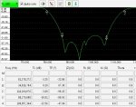
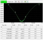
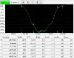
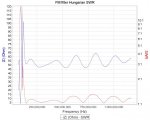
I made some additional plots of the HPN-30118 and also Stridsberg FLT201A and Janielectronics $20 filter from a Hungarian guy on Ebay FM Notch Filter for RTL SDR HAM radio Receiver | eBay
View attachment 75579
View attachment 75580

View attachment 75581
View attachment 75582

View attachment 75583
View attachment 75584

/Ubbe
 

ka3jjz

Wiki Admin Emeritus
Joined
Jul 22, 2002
Messages
25,391
Location
Bowie, Md.

prcguy

Member
Joined
Jun 30, 2006
Messages
15,344
Location
So Cal - Richardson, TX - Tewksbury, MA
Still not as good as the MiniCircuits. I have a huge FM broadcast signal at 88.1MHz here and the 30dB or so the PAR offers is not enough for me. For example, I have a Discone feeding a MiniCircuits FM trap with its 50+ dB of attenuation at 88MHz then feeding an 11dB gain preamp, resulting in a signal that's -34dBm at the end of 150ft of coax. Without any FM trap my preamp would be trying to spit out about +16dBm with just the 88.1MHz signal, not counting anything else. If I were to swap out my MiniCircuits filter for the PAR the 88.1 signal would be closer to -14dBm into my receiver. I'll take all the FM attenuation I can get!

Might as well add something into the mix that's a bit more familiar...


Mike
 

vagrant

ker-muhj-uhn
Premium Subscriber
Joined
Nov 19, 2005
Messages
3,177
Location
California
I like how the Mini Circuits kicks in at 75 MHz. This makes it a solution while in Japan, as it was probably designed to include that region. Additionally, I am pretty sure I have one of those Radio Shack FM filters. I'll track it down and post those numbers as well. Information is a good thing in order to make informed decisions, or realize why things may not be working so well or at all.

I currently use the RTL-SDR filter inline, but only for a receiver scanning 225 - 400 MHz mil air stuff as its loss is low through there. That particular setup uses an antenna best suited for 225-400 as well as a bandpass filter for 225-400 MHz. It's pretty tight and the RX range is nice with an amp on it. I use a different system for VHF air voice stuff.

I did a quick test between the RTL-SDR and the HPN-30118 this morning while monitoring some traffic on 123.450 MHz on my VHF friendly system. One of the aircraft pilots audio was 100% lost using the RTL-SDR filter with the squelch wide open. There was some slight noise using the HPN-30118, but I could clearly understand everything he said using that filter.

Thank you for reminding me about that Mike. I will note the PAR numbers when I post the Radio Shack filter results. I wish Dale had the numbers starting at 50 and working up to at least 600 MHz, or close to it. Still, better some numbers than none and I believe that filter is around $70.
 
Last edited:

vagrant

ker-muhj-uhn
Premium Subscriber
Joined
Nov 19, 2005
Messages
3,177
Location
California
I did add the result from 450 MHz on the filters I currently have. Anyways, I urge anyone who has a receiver/scanner to take a look at what broadcast stations are near your location. Just enter in your zip code and review the results. It provides results for Canada and international visitors as well. It may detail the station power output and it will at least provide a person with more information for further research. FM stations can pump out a lot of power.

Radio Shack FM Trap $10?
Freq Loss dB
50 = 0.55
75 = 1.49
88 = 6.01
95 = 31.97
107 = 30.68
119 = 1.36
125 = 1.22
150 = 0.42
450 = 0.68
600 = 1.44
RTL-SDR FM Filter $17
Freq Loss dB
50 = 0.26
75 = 1.95
88 = 47.45
95 = 54.95
107 = 59.80
119 = 11.55
125 = 3.13
150 = 0.73
450 = 0.03
600 = 0.17
HPN-30118 AM/FM Filter $50
Freq Loss dB
50 = 0.49
75 = 0.68
88 = 28.06
95 = 43.8
107 = 28.17
119 = 0.70
125 = 0.90
150 = 0.76
450 = 0.62
600 = 1.40
Par FM Filter $70?
Freq Loss dB
88 = 30.20
98 = 51.50
108 = 31.88
120 = 1.43


ZBSF-95+ Bandstop $100
Freq Loss dB
50 = 0.21
75 = 27.10
88 = 51.83
95 = 45.23
107 = 54.08
119 = 1.15
125 = 0.62
150 = 0.27
650 = 0.27
 

ka3jjz

Wiki Admin Emeritus
Joined
Jul 22, 2002
Messages
25,391
Location
Bowie, Md.
Dale is/was a RR member; he's been known to be very responsive to questions. Why not write him and ask? Mike
 

pro92b

Mutated Member
Premium Subscriber
Joined
Jun 27, 2002
Messages
1,910

dlwtrunked

Member
Premium Subscriber
Joined
Dec 19, 2002
Messages
2,128
Still not as good as the MiniCircuits. I have a huge FM broadcast signal at 88.1MHz here and the 30dB or so the PAR offers is not enough for me. For example, I have a Discone feeding a MiniCircuits FM trap with its 50+ dB of attenuation at 88MHz then feeding an 11dB gain preamp, resulting in a signal that's -34dBm at the end of 150ft of coax. Without any FM trap my preamp would be trying to spit out about +16dBm with just the 88.1MHz signal, not counting anything else. If I were to swap out my MiniCircuits filter for the PAR the 88.1 signal would be closer to -14dBm into my receiver. I'll take all the FM attenuation I can get!

Agree. I tried the MiniCircuits, PAR, RadioShack, and Stridsberg. The MiniCircuits easily won (I even ordered a spare despite the price). The RadioShack and similar designed/manufactured do not sufficiently attenuate the lower end of the FM broadcast band.
 

prcguy

Member
Joined
Jun 30, 2006
Messages
15,344
Location
So Cal - Richardson, TX - Tewksbury, MA
The Stridsberg doesn't look all that good.

Stridsberg makes a filter for FM, their model FLT201A, $98 - $115 depending on connector option.

I don't own this filter and mention it only to add to the list of vendors identified above.
 

pro92b

Mutated Member
Premium Subscriber
Joined
Jun 27, 2002
Messages
1,910
Mini-Circuits publishes a detailed chart of performance for the ZBSF-95+. Unfortunately it shows worse performance than the ZBSF-95+ datasheet. At 107 MHz the difference is over 10.4 dB. Until someone can measure a ZBSF-95+, it is not clear what its performance is in the upper half of the FM band.

Filters.gif
 

prcguy

Member
Joined
Jun 30, 2006
Messages
15,344
Location
So Cal - Richardson, TX - Tewksbury, MA
I have a MiniCircuits ZBSF-95+ and gave it a quick sweep before installing and it seemed to match the data sheet.

Mini-Circuits publishes a detailed chart of performance for the ZBSF-95+. Unfortunately it shows worse performance than the ZBSF-95+ datasheet. At 107 MHz the difference is over 10.4 dB. Until someone can measure a ZBSF-95+, it is not clear what its performance is in the upper half of the FM band.

View attachment 75610
 

vagrant

ker-muhj-uhn
Premium Subscriber
Joined
Nov 19, 2005
Messages
3,177
Location
California
Good catch. Interesting that Mini Circuits own data does not match up as 10dB is a notable difference. Still, the numbers overall and at 118 MHz and up look good comparatively against the other filters.

I use an HPN-30118 in the vehicle. I have been pleased with its performance over the years. For just $50 more, the ZBSF-95+ would be best suited for use at my home with the improved receivers and antenna that monitor VHF air and up as well as below. To each their own of course. Right tool for the right job kind of thing. The numbers help anyone who needs an FM filter.
 

prcguy

Member
Joined
Jun 30, 2006
Messages
15,344
Location
So Cal - Richardson, TX - Tewksbury, MA
I'll probably order another MiniCircuits filter and will sweep and post data if I get it.

Good catch. Interesting that Mini Circuits own data does not match up as 10dB is a notable difference. Still, the numbers overall and at 118 MHz and up look good comparatively against the other filters.

I use an HPN-30118 in the vehicle. I have been pleased with its performance over the years. For just $50 more, the ZBSF-95+ would be best suited for use at my home with the improved receivers and antenna that monitor VHF air and up as well as below. To each their own of course. Right tool for the right job kind of thing. The numbers help anyone who needs an FM filter.
 

pro92b

Mutated Member
Premium Subscriber
Joined
Jun 27, 2002
Messages
1,910
Good catch. Interesting that Mini Circuits own data does not match up as 10dB is a notable difference. Still, the numbers overall and at 118 MHz and up look good comparatively against the other filters.
In thinking about this a bit more, I think the performance at 118 - 136 is actually the cause of the data discrepancy. Mini-Circuits was careful to minimally impact the civil air band and cut the upper frequency of the notch filter very fine. Due to component tolerances there is some shift in the upper cutoff from one filter sample to another. Since the slope of the response curve is very steep, small shifts in the curve cause comparatively large changes in attenuation at 107 MHz.

So which published data points at 107 MHz are correct? It is probably true that both are correct and the 10dB variation (or more) can be expected in production due to component tolerances. If you are trying to suppress a flamethrower FM station around 107 MHz, ten different ZBSF-95+ filters would probably give ten different amounts of attenuation with a spread of 10 dB or more.

In my case I monitor 150 MHz and up so the RTL-SDR filter is best for me. I agree that publishing the numbers will allow someone to pick what works for his unique requirements.
 

vagrant

ker-muhj-uhn
Premium Subscriber
Joined
Nov 19, 2005
Messages
3,177
Location
California
It is probably true that both are correct and the 10dB variation (or more) can be expected in production due to component tolerances.
Oh hell no. 10 dB is massive and I would not "expect" that difference from one to another of the same model. Still, my experience is minimal with filters and I sweep everything as of late.
 

prcguy

Member
Joined
Jun 30, 2006
Messages
15,344
Location
So Cal - Richardson, TX - Tewksbury, MA
I agree, the filter to filter difference should be minimal and I would expect within +/-2dB or so. MiniCircuits usually publishes minim specs and typical specs which is closer to what you will receive. This filter doesn't seem to have both specs.

Oh hell no. 10 dB is massive and I would not "expect" that difference from one to another of the same model. Still, my experience is minimal with filters and I sweep everything as of late.
 

pro92b

Mutated Member
Premium Subscriber
Joined
Jun 27, 2002
Messages
1,910
I didn't explain it well. The picture shows what I am trying to convey. A small shift in the location of the cutoff portion of the curve results in a large attenuation shift. This only happens on the steep slope of the curve, at the edges of attenuation. For our discussion F5 is 107 MHz. Small changes in the curve result in large changes in insertion loss, the red lines. The steeper the slope of the curve, the greater the shift in insertion loss.

Bottom line is that Mini-Circuits placed the cutoff just inside the very edge of the FM band and it results in variable attenuation at the top end of the FM band. This is only an issue at the top of the FM band. I would expect almost no variation in attenuation in the flat part of the curve between F4 and F5.

Filter Shift.jpg
 

nanZor

Active Member
Joined
May 28, 2009
Messages
2,807
@prcguy ..

You might be lucky at the bottom of the band with the flamethrower at 88.1. My thought is that *additional* attenuation beyond the mini-circuits filter, and open-ended quarter-wave stub at the input to your desired receiver (made from GOOD coax/hardline) might provide a bit of additional attenuation without the insertion loss starting to affect the bottom of the vhf air-band.

If the flamethrower was at 107 mhz, nah, I probably wouldn't try the addition of a stub after the filters.. But at 88.1 - maybe...
 
Status
Not open for further replies.
Top