Yaesu: FT-101E noise pulse/meter spike

Status
Not open for further replies.

Champo

Member
Joined
May 4, 2021
Messages
68
I have a Yaesu FT-101E that the meter will spike (along with a pop in the speaker) when you unkey. Rather than the needle dropping on the meter after you unkey it will actually spike up about twice the height of the meter reading before dropping back to the S unit i.e. S1 in most cases. There is also a pop and a significant spike that occurs when cycling the band switch to AM. If you cycle back off to any other mode and then cycle back to AM quickly the spike will be very minimal. If you wait about 10 to 20 seconds before you cycle back to AM the loud pop and significant meter spike occurs. It almost seems like a capacitor is discharging a pulse and once it does the meter spike is minimal but if you give it a few seconds it charges back up and releases the pulse. This pulse is also noticeable in a nearby receiver. Any thoughts as to where to concentrate would be appreciated. The radio has been recapped and aligned. I double checked my cap installation and cannot find any caps that are incorrect in value or reversed. It also has an AM filter and mod. I tried the speaker pop mod in the service manual to pcb 1183 with no luck.

Jacob
 
Last edited:

K4EET

Chaplain
Joined
Feb 18, 2015
Messages
2,178
Location
Severn, Maryland, USA
<snip> This pulse is also noticeable in a nearby receiver. <snip>
Good morning Jacob,

That is a clue. Now to determine if the pulse is over the air via antennas/proximity or via the power lines by a noise pulse. Is the transmitter momentarily keying when you rotate the mode knob to AM? Do you see a noise spike on the AC power line (if you have an oscilloscope or some way of detecting the spike)? Obviously, systematic troubleshooting is going to be required. What test equipment might you have or could you take the transceiver to a friend’s house that has test equipment?

Keep us posted. Have a great weekend!

73, Dave K4EET
 

Champo

Member
Joined
May 4, 2021
Messages
68
Good morning Jacob,

That is a clue. Now to determine if the pulse is over the air via antennas/proximity or via the power lines by a noise pulse. Is the transmitter momentarily keying when you rotate the mode knob to AM? Do you see a noise spike on the AC power line (if you have an oscilloscope or some way of detecting the spike)? Obviously, systematic troubleshooting is going to be required. What test equipment might you have or could you take the transceiver to a friend’s house that has test equipment?

Keep us posted. Have a great weekend!

73, Dave K4EET
Good Morning Dave,

I'm dragging butt a bit today but I've made some significant progress since my last post.

Muting Receiver:
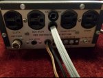
You can indeed mute a second receiver with the ACC plug connection at pins 8 and 9. If you are also running an amplifier you might have a problem with an older amp like the SB-230 that has high voltage at the relay connection as these pins are also used to key the amplifier. I have an external soft key that I tried installing between the FT-101E and the amp in hopes of isolating the amp without success. This "trial and error" was done prior to me correcting the meter spike which I'll talk about later. I have an Ameco PT-1 that I was going to try to use but it seemed to amplify the speaker pops I was having in the Yaesu (keying and unkeying) as well as buzzing that occurred in the receiver when the muting function on the Ameco was used. This is why I initially looked to use the FT-101E directly with the FRG-7.

Meter spike/pulse:
The other scenario I was having was a massive spike that would occur when you would unkey or even when switching between AM and the other modes. This spike would also be accompanied by a loud pop in the speakers of both the FT-101E as well as the FRG-7... even when the later wasn't connected. There is a mod to the PCB 1183 that is discussed in the service manual that requires adding a ceramic and electrolytic cap to the board and removing an electrolytic from the underside of the PCB socket. Unfortunately this had no affect on either the pop or the meter spike. I tried reseating all of the boards as well with no luck.

At this point, with very few options left, I decided to pull all of the boards and try cleaning the board fingers and sockets with DeoxIT...again. I did this when I first acquired the radio 7 months ago but figured screw it.... what do I have to lose? I took a small paint brush and "painted" the sockets with DeoxIT and then sprayed and wiped the board fingers. I then took card stock and ran it in and out of the sockets. I did get some black on some of them. I'm not sure if it is carbon build up, dust, combo etc but apparently my initial cleaning wasn't as thourough as it could have been. For anyone trying to clean the sockets just know that soaking the card stock in DeoxIT doesn't work as it loses its regidity.

I hooked the Yaesu back up and low and behold no meter spike when unkeying. The spike when switching modes was also significantly reduced along with the pop it produces. If you rotate the mode knob slowly it almost eliminates it entirely. I'd removed the cable that I'd connected to the ACC port for the receiver by this point so to save me some time I connected the FT-101E and the FRG-7 to the Ameco PT-1. Everything worked just as it should minus a small pop upon key up that's heard in both the FT-101E speaker as well as the FRG-7 speaker. Other than the 4PDT relay in the Ameco the two units share no connections. I'm going to try disconnecting the muting cables from the FRG-7 today to see if the pop upon key up is still heard. If so the FRG-7 is picking up that pop from the FT-101E. This occurs even if no carrier or gain is used so it's simply the actuation of the relay causing it.

The last step was to introduce the amp back into the equation. I decided to add the soft key between the amp and the PT-1 just for the hell of it. As of last night at 2am everything appeared to work properly save the small speaker pop in both the FT-101E and FRG-7 upon key up. I decided to reverse the mod that was done to the PCB 1183 to see what would happen. Well I can tell you that the mod does work! A very substantial pop returned after reversing it so I reinstalled the mod and that's where I left it as of 3am last night. Some more thorough testing needs to be done today to verify my findings are consistent and not a fluke as I was fried by 3 am. I have a spare set of relays that I might throw at it for the hell of it to see if I can kill the speaker pop on key up. If I can't I'll have to live with it as I'm out of possibilities unless someone has any recommendations.

Unfortunately I can't confirm if muting the receiver directly with the the FT-101e while using an amp will work successfully but it very well might.

I hope you have a great weekend too Dave. Thanks for the help!

Jacob
 

Attachments

  • Screenshot_20220402-122323_Gallery.jpg
    Screenshot_20220402-122323_Gallery.jpg
    201.2 KB · Views: 7
  • Screenshot_20220402-122333_Gallery.jpg
    Screenshot_20220402-122333_Gallery.jpg
    191.2 KB · Views: 7
  • Screenshot_20220402-122354_Gallery.jpg
    Screenshot_20220402-122354_Gallery.jpg
    97.8 KB · Views: 7
  • Screenshot_20220402-122407_Gallery.jpg
    Screenshot_20220402-122407_Gallery.jpg
    107.1 KB · Views: 6

K4EET

Chaplain
Joined
Feb 18, 2015
Messages
2,178
Location
Severn, Maryland, USA
Hi Jacob,

Let me commend you for writing such a detailed report. That is very much appreciated. If everyone would write reports like that, we would all be in a better position to troubleshoot things. All too often I read things like “My speaker is making annoying popping sounds. Any ideas on to make it stop?” When that limited amount of information is given, I’m tempted to respond with “Unplug the speaker.” LOL! In your thread, you have done an excellent job in describing the equipment configuration, what you’ve done so far in the way of troubleshooting and included any additional information that you think might help us out. I thank you again for that. It took time to write down the details but you saved us a lot of time by not having to guess. Have I told you that I appreciate that?

Sounds like you are making some good progress in the troubleshooting effort. I don’t have anything worthwhile to contribute at this point other than to say keep up the good work! I’ll be curious to know if a different relay helped any. As for troubleshooting at 2 AM or 3 AM, don’t burn yourself out.

Finally, the Yaesu FT-101E transceiver is a rig that I would love to have in my shack. I have wanted one since the early 1970s. I have operated them and helped people troubleshoot them but I’ve never found one in decent condition around here. I don’t want to pay for shipping because those radios are heavy due to the built-in power supply.

73 my friend, Dave K4EET
 

Champo

Member
Joined
May 4, 2021
Messages
68
Regrettably I fired off that message prematurely. When I fired it up today the pop was substantial in the speaker. It was much more pronounced than last night. It was also still present in FRG-7 receiver. There was also significant feedback when modulation was introduced. That part was my fault. I was in a hurry and used unshielded wire. Swapping it to a section of coax corrected that aspect of it. I removed the Ameco from the station as well. I suspected this might be my pop culprit at the moment and it turned out to be correct. Low and behold no pop in either speaker and no feedback in the receiver once it was out. I wired the coax up directly to the ACC port pins 8 and 9 and the receiver accordingly. Using the soft key in between the amp and the FT-101E I had everything working perfectly. Unfortunately the soft key was acting as an isolator and I think it just failed. Having the coax going to the transceiver is now keying the amp so I need to find a way to isolate it in some way. With the amp and FT-101E connected without the coax connection to the receiver and they function normally. No amp in play (on but not switched in line) and the transceiver and receiver play nice. All three in the mix and the connection at the receiver keys the amp relay the moment it is switched in line. Sigh..... that's my story for the day lol.

As for the radio. I got really lucky with it because it was only about 2 hours from me and in excellent shape. It included the SP-101 speaker as well. When I picked it up it hadn't been used in 25 years. It's been an arduous journey to get to this point. There have been many moments that I truly considered throwing it from my second story window. Some related to the radio... others related to things affecting the radio. I feel like I'm on the home stretch though.
 

K4EET

Chaplain
Joined
Feb 18, 2015
Messages
2,178
Location
Severn, Maryland, USA
<snip> There have been many moments that I truly considered throwing it from my second story window. <snip>
If that urge swells to the point of taking real action in response to the stimulus or stimuli, be sure to allow me enough time to arrange for a Public Safety effort to safely catch the free-falling equipment. Response time should only be a matter of minutes. I would catch it myself but I’m in a manual wheelchair 🦽 and can’t propel myself around and catch at the same time. LOL! 😂

Talk to you tomorrow. Have a blessed Sunday.

Dave K4EET
 

Champo

Member
Joined
May 4, 2021
Messages
68
That urge has subsided a bit.... but if it returns I will definitely let you know 😆

Sorry for the late update. I've discovered a few things. To start I made an assumption that I would be able to wire the muting cord to the FT-101E in the same manner that the FR-101 wires in to the FT-101E without researching how the muting function works in the FR-101. It turns out that the FR-101 uses a normally closed contact for receive and mutes when the contact opens up. This is why you use pins 8 and 10 at the ACC plug. The FRG-7 works in reverse with a normally open contact and mutes when the contact is closed. This requires you to use pins 8 and 9 in the ACC plug to mute the receiver. If you don't plan on using an amplifier then you're good to go with this configuration. It will work just fine.

The problem occurs if you try to use an amplifier in conjunction with the FRG-7 because it also uses pins 8 and 9 for the relay keying circuit. The FRG-7 will key the amplifier in this configuration. It took me a bit to figure out why but ultimately I was able to determine that there is 9 VDC present at the muting terminal on the FRG-7 and, since the amp and receiver share the same connections, its a direct feed to the amp.

I haven't had time to revisit this yet but it's simply a matter of preventing the 9 VDC from reaching the amplifier to make the whole setup work in conjunction.
 

K4EET

Chaplain
Joined
Feb 18, 2015
Messages
2,178
Location
Severn, Maryland, USA
Hi Jacob,

No need to apologize. You are the boss making the schedule.

Thanks for the update. I really am interested in following what you are doing because of my affection for the FT-101E transceiver. Sounds like you are making progress in the right direction.

Cheers! Dave
 

Champo

Member
Joined
May 4, 2021
Messages
68
So here is an update on where this project stands. I was unable to develop a successful method for muting the FRG-7 via the FT-101E directly while isolating the 9vdc at the muting connection of the FRG-7 that caused the amplifier relay to key. I was SUCCESSFUL however in muting the FRG-7 by using the microphone which isolates the 9vdc from the FT-101E thus eliminating the 9 vdc problem. I use an amplified Silver Eagle D104 in conjuction with the FT-101E. The FT-101E mic plug only utilizes 3 of the 4 microphone pins...position number 4 being empty. To achieve this it will require modification to the microphone as well as the addition of a wire to the FT-101E.

MIC MOD

The microphone tabs/fingers require modification in order to work. Using a non-modded mic on the FT-101E will not affect anything other than the FRG-7 would be muted upon plugging in the mic. If the FRG-7 were off operation would be normal.

To start, my D104 uses a 4 wire cord so the yellow wire is currently floating and the blue wire is connected to the shield finger (E).

The mic mod is quite simple. There is a separator/isolator that isolates the violent wire (C) finger from the brown wire (D) finger. The first step is to relocate this separator/isolator. It will be moved in between the violet wire (C) finger and audio wire finger (B) which comes from the mic cord. This leaves the violet wire (C) "floating" on my particular mic i.e. no contact made with the brown wire (D) finger. YMMV and the finger may need to be bent to create the necessary space to prevent the brown and violet wire tabs from making contact in the resting position. As can be seen in the attached image, when the ptt switch is depressed the violet wire (C) finger and the brown wire (D) finger will now make contact grounding the violet wire (C) finger. If you trace the violet wire to the amplifier board you will see that it is a dead connection (on my mic) that makes contact with no other components. This wire can be left in place, removed from the finger or removed entirely. In my case I left the wire soldered to the amp board but removed it from the finger to create more room for the next step.

The next step is to relocate the black mic cord wire (J) to the violet wire (C) finger. Now, when the ptt switch is pressed, the black mic wire will ground to the brown wire (D) finger.

RADIO

Now that the mic has been modded, a wire will need to be soldered to the empty position (position 4) of the mic plug on the radio. You will then run this new wire to the ACC (11 pin accessory socket) on the back of the radio. Position 11 of the ACC socket is empty and you will install the new wire at this location. The 500vdc caps are in this location so MAKE SURE that they have been properly discharged! Running a piece of foil, card stock etc around the ACC socket will help to prevent you from damaging nearby wires.

You will now need to install the ground and muting wires that will run to the FRG-7. In my case I used a section of RG8 coax that I had left over from another project. The ground wire will be soldered into position 8 (along with the ground wires for the amplifier relay cable and the ALC cable. The muting wire will get soldered into position 11. Once completed the ACC plug should be wired as such. Position 7 ALC, position 8 Grounds, position 9 amp key and position 11 muting line for the FRG-7.

Now all that is left is to connect the ground and muting cable to the back of the FRG-7. The mic will now mute the FRG-7 when the PTT switch is pressed.
 

Champo

Member
Joined
May 4, 2021
Messages
68
Forgot this.
 

Attachments

  • Screenshot_20220506-141718_Google.jpg
    Screenshot_20220506-141718_Google.jpg
    109.4 KB · Views: 2
Status
Not open for further replies.
Top