Brandon_K
Member
Hi gents. I've recently joined an endurance race team. Aside from acting as driver, mechanic and logistics, I'm also one of the only tech savy guys on the team.
A quick background; They have always been unhappy with their communications between crew, chief and cars (we run 3 cars out of one pit and team). Prior to me coming on they were using a mix of P110's, a CP200 and some old Speedcom branded radio's. Two cars were using single P110's, one car was using a P110 and a CP200 with a battery eliminator with a dual radio switch. The CP200 was the main, but the battery eliminator would tend to lose contact. The driver sometimes wouldn't realize for a while (each driver runs a 2 hour stint). During that time, we would be trying to get him on the radio. He wouldn't come on until he switched over to the backup.
During the last race (14 hours at Daytona), I brought a few banks of my radio's in to use, HT750's and 1250's. I reprogrammed them to match their existing frequencies and away we went. The long and short of it is the team owner was thrilled at the end of the race and actually told me "We wouldn't have won had you not improved the communications". Great, nice little ego boost, but taking 1st place in a 14 hour endurance race with one of our cars was icing on the cake. But, the system still isn't ideal. 2 of the cars still run single radios. Swapping batteries every 4 hours during pit stops isn't ideal. While this is a fairly compact track, other tracks can be a mile or even 2 from pits to a back corner and while 4w is likely enough, stubby antennas on the radios, which are mounted down low behind steel door skins, doesn't fly for some of the other tracks.
So, I've ordered a bunch of PM400's to put in the cars. I'm also going to put a HT750 in each car as the backup radio. I figure we can get 14 hours out of a battery if it's only running idle or Rx instead of the main Tx radio.
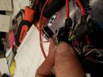
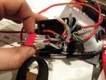
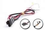
I started planning a dual radio switch in my head. In my head, it should be pretty simple. A 4PDT switch. Each radio connects to each side of the switch (Mic+, Mic-, Spkr+, Spkr-). Center poles connect to a 4\5 conductor TJ101 connector (pretty standard in open wheel racing, used for earbuds and helmet mounted mic), with a PTT switch in series with one of the Mic wires, before it heads to the TJ101 connector. Then it dawned on me that I should open up the existing commercial manufactured dual radio box we have and reverse engineer it. So I did.
For the most part, everything was how I thought in my head. All of the shields are tied together, 4 wires in from each radio, 4 wires out to the TJ101 connector with a PTT inline. Except, there are 2 little cans on each of the radio "input" (to the switch) wires. Each can has 7wires on it (red (tied to nothing), black and white (tied together), then red, blue, green and yellow that run in between the radio wires and the switch. I've been trying to ohm out the box and create a schematic, but I'm having a hard time with it. For example, I'm getting continuity between the Spkr+ and Spkr- pins that would plug into the radio (the 3.5mm). There should be no continuity since there is no speakers/earbuds plugged in. The little can's are labled "PICO-11???". I don't remember what the last 3 digits were, I'll update that tomorrow, the harness is at my shop. Either way, I googled it and came up with exactly nothing. I assume it's some sort of audio transformer, but I have no idea.
The end goal (which will bring me to other questions) is to create our own radio box, for a few reasons. Primarily, every communication company out there that specializes in racing only deals primarily with 2 pin Motorola. I suppose I could use CP200's, but why when I have a few dozen HT750's and HT1250's. Further, they charge rather high prices for what they are. Nearly $300 for a 4PDT switch, two 2 pin plugs, a 3 pin miniXLR connector (for PTT switch input) and a TJ101 connector. I can scavenge pretty much everything I need from existing junk, except for the TJ101 connectors and the 3 pin miniXLR.
I've never been a huge fan of the 2 pin connector, especially in something "mission critical" like endurance racing. Plus, the 2 pin adapters that I have for my HT's are pretty low quality and simply don't mate well to the 2 pin plug. So, I want to make it so that Radio 1 goes down to the PM400 and Radio 2 has a HT multipin connector on it. I may even make the inputs with miniXLR so I can use interchangeable cables between the box and the radio, should we decide to change the radio setup or a PM400 dies, etc. Going from the box to the PM400 is simple enough, it's just an RJ45. I was going to sacrifice a few speaker mic's to obtain a HT connector with coil cord for the HT750 acting as the backup radio.
I'll have a PM400 at the hot pit with a antenna on a short mast, plus a PM400 back at the garage.
So, first and foremost, do any of you pro's (that have likely been tinkering with radio's longer than I've been alive) want to take a guess to what the little can is?
Second, is there are reason I shouldn't be using the mic input on the PM400 versus the accessory connector on the back?
Third, is there any reason I wouldn't be able to have a PM400 and a HT-series radio co-exist? I suspect the mic gains could possibly be different between them? I'm planning on both radio's running roof or trunk lid mounted antennas (specifically, these Antenex models that came with the radio's. I still need to grab some HT > BNC antenna adapters.
Does anyone have any hints, tips or tricks for me? I may have a few PCB's made to have all of the wiring terminate to instead of the rat's nest that was stuffed in the box.
Any help would be greatly appreciated. Sorry for the novel of a post.
A quick background; They have always been unhappy with their communications between crew, chief and cars (we run 3 cars out of one pit and team). Prior to me coming on they were using a mix of P110's, a CP200 and some old Speedcom branded radio's. Two cars were using single P110's, one car was using a P110 and a CP200 with a battery eliminator with a dual radio switch. The CP200 was the main, but the battery eliminator would tend to lose contact. The driver sometimes wouldn't realize for a while (each driver runs a 2 hour stint). During that time, we would be trying to get him on the radio. He wouldn't come on until he switched over to the backup.
During the last race (14 hours at Daytona), I brought a few banks of my radio's in to use, HT750's and 1250's. I reprogrammed them to match their existing frequencies and away we went. The long and short of it is the team owner was thrilled at the end of the race and actually told me "We wouldn't have won had you not improved the communications". Great, nice little ego boost, but taking 1st place in a 14 hour endurance race with one of our cars was icing on the cake. But, the system still isn't ideal. 2 of the cars still run single radios. Swapping batteries every 4 hours during pit stops isn't ideal. While this is a fairly compact track, other tracks can be a mile or even 2 from pits to a back corner and while 4w is likely enough, stubby antennas on the radios, which are mounted down low behind steel door skins, doesn't fly for some of the other tracks.
So, I've ordered a bunch of PM400's to put in the cars. I'm also going to put a HT750 in each car as the backup radio. I figure we can get 14 hours out of a battery if it's only running idle or Rx instead of the main Tx radio.
I started planning a dual radio switch in my head. In my head, it should be pretty simple. A 4PDT switch. Each radio connects to each side of the switch (Mic+, Mic-, Spkr+, Spkr-). Center poles connect to a 4\5 conductor TJ101 connector (pretty standard in open wheel racing, used for earbuds and helmet mounted mic), with a PTT switch in series with one of the Mic wires, before it heads to the TJ101 connector. Then it dawned on me that I should open up the existing commercial manufactured dual radio box we have and reverse engineer it. So I did.
For the most part, everything was how I thought in my head. All of the shields are tied together, 4 wires in from each radio, 4 wires out to the TJ101 connector with a PTT inline. Except, there are 2 little cans on each of the radio "input" (to the switch) wires. Each can has 7wires on it (red (tied to nothing), black and white (tied together), then red, blue, green and yellow that run in between the radio wires and the switch. I've been trying to ohm out the box and create a schematic, but I'm having a hard time with it. For example, I'm getting continuity between the Spkr+ and Spkr- pins that would plug into the radio (the 3.5mm). There should be no continuity since there is no speakers/earbuds plugged in. The little can's are labled "PICO-11???". I don't remember what the last 3 digits were, I'll update that tomorrow, the harness is at my shop. Either way, I googled it and came up with exactly nothing. I assume it's some sort of audio transformer, but I have no idea.
The end goal (which will bring me to other questions) is to create our own radio box, for a few reasons. Primarily, every communication company out there that specializes in racing only deals primarily with 2 pin Motorola. I suppose I could use CP200's, but why when I have a few dozen HT750's and HT1250's. Further, they charge rather high prices for what they are. Nearly $300 for a 4PDT switch, two 2 pin plugs, a 3 pin miniXLR connector (for PTT switch input) and a TJ101 connector. I can scavenge pretty much everything I need from existing junk, except for the TJ101 connectors and the 3 pin miniXLR.
I've never been a huge fan of the 2 pin connector, especially in something "mission critical" like endurance racing. Plus, the 2 pin adapters that I have for my HT's are pretty low quality and simply don't mate well to the 2 pin plug. So, I want to make it so that Radio 1 goes down to the PM400 and Radio 2 has a HT multipin connector on it. I may even make the inputs with miniXLR so I can use interchangeable cables between the box and the radio, should we decide to change the radio setup or a PM400 dies, etc. Going from the box to the PM400 is simple enough, it's just an RJ45. I was going to sacrifice a few speaker mic's to obtain a HT connector with coil cord for the HT750 acting as the backup radio.
I'll have a PM400 at the hot pit with a antenna on a short mast, plus a PM400 back at the garage.
So, first and foremost, do any of you pro's (that have likely been tinkering with radio's longer than I've been alive) want to take a guess to what the little can is?
Second, is there are reason I shouldn't be using the mic input on the PM400 versus the accessory connector on the back?
Third, is there any reason I wouldn't be able to have a PM400 and a HT-series radio co-exist? I suspect the mic gains could possibly be different between them? I'm planning on both radio's running roof or trunk lid mounted antennas (specifically, these Antenex models that came with the radio's. I still need to grab some HT > BNC antenna adapters.
Does anyone have any hints, tips or tricks for me? I may have a few PCB's made to have all of the wiring terminate to instead of the rat's nest that was stuffed in the box.
Any help would be greatly appreciated. Sorry for the novel of a post.