Andy3
Member
A new phone mast was erected just down the road recently, and now they've turned the darned thing on. One of my interests is eavesdropping on what people are doing with their wireless mics, headphones and other low-power links in the UK allocation around 860 MHz, but my AR-DV1 receiver is not pleased by the new BIG signals on ~950 MHz!
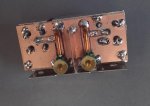
So I decided to build a band-pass filter. With the aid of my Signal Hound spectrum analyser and tracking generator I but this. It's a coupled bandpass pair, and the degree of coupling was adjusted by altering the central screen between the sections.
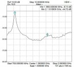
It works great, putting plenty of attenuation in above and below the wanted band and only a 6 dB in-band loss, which could probably be reduced further with a bit of effort.
The two L's are just about 1 inch of thick copper wire. The ground ends are pushed through holes in the double-sided pcb and soldered both sides. The ground legs of the trimmers (10pF) are also soldered both sides, as are the F-conectors. There are copper foil straps to the tinplate box. Tap points for the in/out connections are about 1/3 of the way up from ground.
So I decided to build a band-pass filter. With the aid of my Signal Hound spectrum analyser and tracking generator I but this. It's a coupled bandpass pair, and the degree of coupling was adjusted by altering the central screen between the sections.
It works great, putting plenty of attenuation in above and below the wanted band and only a 6 dB in-band loss, which could probably be reduced further with a bit of effort.
The two L's are just about 1 inch of thick copper wire. The ground ends are pushed through holes in the double-sided pcb and soldered both sides. The ground legs of the trimmers (10pF) are also soldered both sides, as are the F-conectors. There are copper foil straps to the tinplate box. Tap points for the in/out connections are about 1/3 of the way up from ground.