Homemade satcom antenna

Status
Not open for further replies.

prcguy

Member
Joined
Jun 30, 2006
Messages
15,368
Location
So Cal - Richardson, TX - Tewksbury, MA
The 20 to 60 deg range is based on typical satellite look angles within the Continental US (CONUS) and focusing as much omni directional gain at those angles as possible. The X-Wing does have gain but I'm attending the Dayton Hamvention this weekend and don't have my old files with me to look that up.

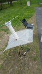
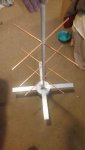
The design allows the antenna to sit on flat ground pointing straight up and be useable on as many UHF military satellite as possible within the US or places of similar Latitude above or below the equator such as parts of EU, South America, Australia. etc.

A preamp can help depending on receiver and length/type of feed line. I get great performance using about 20ft of RG-58 coax and a Yupiteru MVT-7100 receiver. YMMV.

The MT X-Wing is designed as a receive only antenna and would have high VSWR and degraded circular polarization in the uplink portion of the band.
prcguy

Hmmmm? That 20-60 degree range is what the Amsat folks claim is normal operation, especially with handheld antenna contacts.

I doubt that the X wing would have any gain, however. Would that be omni-directional too? Perhaps a preamp would help.

This is primarily a receive only antenna, Ever been used to transmit?
 

RFBOSS

Member
Joined
Jul 31, 2016
Messages
88
Remember that noise figure may be more important than gain.

In simple terms the noise figure of the first device in line (the RF preamplifier) determines the minimum noise figure for cascaded RF amplifiers. That is one RF amplifier following another. In this application these would be the external RF preamplifier and the the first RF stage of the receiver being used.

At maximum gain, the amplifier in the link above has a rated noise figure of 7.4dB. That is not a very good number (lower is better). A low noise amplifier can have noise figure of less than 1dB (this is a good number).

Using the amplifier above, even the the receiver has a noise figure of 2dB (a relatively good number) the overall noise figure will still be greater than 7.5dB (not a very good number).

Unless one is using an RF amplifier to overcome feed line loss, in general there will very little improvement in signal performance if the noise figure of the amplifier is not lower than the noise figure of the receiver.

The device above uses attenuation prior to amplification for gain control. The noise figure will degrade some at lower gain settings.

The LNA-580 preamp referenced above has a noise figure of less than 1dB (a very good number). I would not wast my time trying RF preamplifiers with high noise figures (a bad thing).
 

prcguy

Member
Joined
Jun 30, 2006
Messages
15,368
Location
So Cal - Richardson, TX - Tewksbury, MA
I've never seen a receiver with a noise figure in the 2dB range, I think 5dB minimum and more like 7dB would be more common.

If you have lots of feed line loss then a 7dB NF preamp could improve reception as it will make up for some of the feed line loss by setting the system noise figure at a point closer to the antenna and before the feed line loss. Although I would never consider something as dreadful as a 7dB NF preamp.
prcguy

Remember that noise figure may be more important than gain.

In simple terms the noise figure of the first device in line (the RF preamplifier) determines the minimum noise figure for cascaded RF amplifiers. That is one RF amplifier following another. In this application these would be the external RF preamplifier and the the first RF stage of the receiver being used.

At maximum gain, the amplifier in the link above has a rated noise figure of 7.4dB. That is not a very good number (lower is better). A low noise amplifier can have noise figure of less than 1dB (this is a good number).

Using the amplifier above, even the the receiver has a noise figure of 2dB (a relatively good number) the overall noise figure will still be greater than 7.5dB (not a very good number).

Unless one is using an RF amplifier to overcome feed line loss, in general there will very little improvement in signal performance if the noise figure of the amplifier is not lower than the noise figure of the receiver.

The device above uses attenuation prior to amplification for gain control. The noise figure will degrade some at lower gain settings.

The LNA-580 preamp referenced above has a noise figure of less than 1dB (a very good number). I would not wast my time trying RF preamplifiers with high noise figures (a bad thing).
 

RFBOSS

Member
Joined
Jul 31, 2016
Messages
88
In my other hobby, stereo equipment, it is not unusual for for a quality receiver to have a noise figure in the less than 4 dB range.

But when a properly aligned stereo receiver (in the mono mode) can have a noise figure of say less than 5 dB and as low as 3dB, again I expect more from a receiver.

The point is this. For example if a receiver has a noise figure of 7 dB and is used with an amplifier with a 7 dB noise figure it is only going to supply more of the same, unless it might help to over come feed line loss. A point I made in my post.

If that same receiver is used with a preamp with 25 dB of gain and a 2 dB noise figure it will lower the overall noise figure to about something less than 3 dB in the real world.

Again to be clear, the point of my first post is that using an amplifier with a poor noise figure (the one that was linked to 7.4 dB) will not improve even a receiver with a 2 dB noise figure, it was not to start a discussion of receiver noise figures in particular.

For an RF amplifier to be effective, it should have a noise figure less than the receiver. Again that is the point that I made in my previous post.

Below is some information from Brian Beezley's web site.

Note the noise figure of the receiver (measured). It is a little less than 4 dB, but it is not the best receiver in terms of noise figure out there and this is just consumer grade electronics.

I have this discussion all the time on some of the stereo audio boards. A person will want to receive a weak FM station, purchase an RF amplifier of some sort because it has 35 or 40 dB of gain and then wonder why it did not help when the noise figure was as much as 10 dB (cheap Chinese made TV distribution amplifiers and so on).

The very bottom picture is the measured noise figure (ARRL Labs) of an Icom IC-9100.
 

Attachments

  • NOISE FIGURE.jpg
    NOISE FIGURE.jpg
    19.3 KB · Views: 1,370
  • NOISE FIGURE A.jpg
    NOISE FIGURE A.jpg
    74.6 KB · Views: 1,509
  • ICOM IC-9100 NOISE FIGURE..JPG
    ICOM IC-9100 NOISE FIGURE..JPG
    22.5 KB · Views: 1,371

thewrench002

Member
Premium Subscriber
Joined
Sep 12, 2012
Messages
100
Location
old town, maine
The MT X-wing project antenna works better than a $7,000 military Trivec X-wing within CONUS, I've measured them both.

so if the x wing is great then why does the military not use it?.... i have plans from the cross yagi and helical designs that i will be building this summer... I'm not sure where you live prcguy but here in maine i have to angle the x wing.. i will post afew pics when i get done testing it... it does work but not as good as a cross yagi that i have seen work first hand...
 

prcguy

Member
Joined
Jun 30, 2006
Messages
15,368
Location
So Cal - Richardson, TX - Tewksbury, MA
The military use lots of X-wing satcom antennas, any vehicle or low speed aircraft with satcom will usually have one. Problem is the military versions are a crossed dipole about 1/4 wavelength over a ground plane and they point straight up. You have to be within about +/- 30 deg of a satellite straight above you to make use of their advertised gain, which is unlikely within the US except for maybe Brownsville, TX due to satellite locations.

The MT X-wing has elements close to 1/2 wavelength above a reflector which bring the pattern within a range that can be used almost anywhere in the US by just pointing it straight up. The MT X-wing has a null straight up and slightly less gain than the military version but it makes better use of its gain lobe than the military version within the US.

If you are receiving one of the UHF milsats that's below about 20deg off the horizon with an MT X-wing, then you may have to tilt it towards the satellite to bring the gain lobe down where it see's the satellite better. Another thing is a DIY project antenna might not get built just like the prototypes and performance may suffer.
prcguy


QUOTE=john6483;2768818]
The MT X-wing project antenna works better than a $7,000 military Trivec X-wing within CONUS, I've measured them both.

so if the x wing is great then why does the military not use it?.... i have plans from the cross yagi and helical designs that i will be building this summer... I'm not sure where you live prcguy but here in maine i have to angle the x wing.. i will post afew pics when i get done testing it... it does work but not as good as a cross yagi that i have seen work first hand...
 

thewrench002

Member
Premium Subscriber
Joined
Sep 12, 2012
Messages
100
Location
old town, maine
so after playing around with it and making some modifications to it... i got it working ok with the orange dongle from flightaware pretty well...here are some pics of the out come.. i did try it both ways with the 48"x 48" and there was no change.. the wooden dowels are 36"x 3/4"
 

Attachments

  • 18698797_407898076263591_1645551800_o.jpg
    18698797_407898076263591_1645551800_o.jpg
    76.9 KB · Views: 1,647
  • 18699039_407899042930161_2146035001_o.jpg
    18699039_407899042930161_2146035001_o.jpg
    68.6 KB · Views: 1,422
  • 18720802_407898166263582_1493776140_o.jpg
    18720802_407898166263582_1493776140_o.jpg
    65.2 KB · Views: 1,369
  • 18742328_407898182930247_1896829179_o.jpg
    18742328_407898182930247_1896829179_o.jpg
    84.2 KB · Views: 1,647

prcguy

Member
Joined
Jun 30, 2006
Messages
15,368
Location
So Cal - Richardson, TX - Tewksbury, MA
Nice job! When you say you tried it both ways with no change, are you talking about the coax phasing harness connections? If so, when they are made correctly you will have a huge difference in receiving the UHF satellites where they will go from a strong signal to basically nothing when your revers the F connectors at the base of the dipoles.

If swapping those has little difference then the lengths are not correct and the antenna is more linear polarized instead of right hand circular to match the satellite downlink.
prcguy


so after playing around with it and making some modifications to it... i got it working ok with the orange dongle from flightaware pretty well...here are some pics of the out come.. i did try it both ways with the 48"x 48" and there was no change.. the wooden dowels are 36"x 3/4"
 

thewrench002

Member
Premium Subscriber
Joined
Sep 12, 2012
Messages
100
Location
old town, maine
so i wanted to do some playing around.. gained a little bit with 3 cross yagi 15" copper...1/4" . i can say i'm done playing with this one and building a helical antenna for satcomms...
 

Attachments

  • 18901147_411571449229587_688092101_o.jpg
    18901147_411571449229587_688092101_o.jpg
    81.3 KB · Views: 1,494
  • 18817423_411578265895572_262429604_o.jpg
    18817423_411578265895572_262429604_o.jpg
    39.8 KB · Views: 1,952

prcguy

Member
Joined
Jun 30, 2006
Messages
15,368
Location
So Cal - Richardson, TX - Tewksbury, MA
Looks nice but if you are using the MT-X-wing dimensions and phasing harness it won't benefit. There is a big null in gain in line with the elements you added because the gain lobe is optimized for the antenna pointing straight up and looking at the satellites off to the side between a 20 and 60deg angle upward. In other words there should be little to no signal when you point the antenna at a satellite in a conventional way.

Another problem is the phasing harness also offsets the roughly 70ohm impedance of the dipole elements and helps match that to 50ohms in addition to creating a 90deg phase shift to make the antenna circular polarized. Adding parasitic elements close to the dipole elements will detune them throwing off the match and probably degrading the circular polarization.

To work as a conventional point and shoot satellite antenna you would have to change the spacing from the dipole elements to reflector to about 10", design a new phasing harness and retune the dipole elements because they will be less than 50ohms being closer to the reflector and parasitic elements.

Or you could use the X-wing as intended and tilt it slightly to the south to improve reception from your location at the upper latitude of its design limits.
prcguy

so i wanted to do some playing around.. gained a little bit with 3 cross yagi 15" copper...1/4" . i can say i'm done playing with this one and building a helical antenna for satcomms...
 

prcguy

Member
Joined
Jun 30, 2006
Messages
15,368
Location
So Cal - Richardson, TX - Tewksbury, MA
Where you live all the satellites are way south of you and either south east or south west. For the 22.5W slot you would point a Trivec type antenna roughly 21 deg up from the horizon at a compass heading of 140 deg magnetic. For the 103 and 105W slots point 28 deg up and 241deg magnetic. Or just tilt the X-wing about 15-20deg south to pick up everything since you are at the design limits of that antenna.
prcguy


Trivec Avant AV-2055-3 Lightweight SATCOM Antenna, AV2055 harris antenna | eBay

will be alot less problems just to get this.. seem how most of the satellites i wanna listen to are over the north west of me... with only afew to the south...
 

prcguy

Member
Joined
Jun 30, 2006
Messages
15,368
Location
So Cal - Richardson, TX - Tewksbury, MA
Ok, to my knowledge the US has no UHF mil sats in anything but geosynchronous orbit. So tell us what UHF satellites you can pick up pointing north? What frequency?
prcguy

Edit:
I'm not saying I'm an expert on satellites, but I've worked in the business for many years and just got back from 3 weeks at a remote site building and testing several large satellite antennas. Here is a pic of one system at the site heavily cropped to hide its location. Guess what this might be, and I assure you its not pointing north.....

you are wrong.. MERIDIAN satellites are north northwest of me... LIVE REAL TIME SATELLITE TRACKING - WHAT'S UP IN YOUR SKY shows most if not all satellites in orbit...
 

Attachments

  • satcom shelter.JPG
    satcom shelter.JPG
    76.5 KB · Views: 1,282
Last edited:

Squelchtail

Member
Joined
Nov 23, 2015
Messages
18
Satcom antenna

Here is plans for another satcom antenna
 

Attachments

  • IMG_0091.JPG
    IMG_0091.JPG
    134.7 KB · Views: 574
Status
Not open for further replies.
Top