How not to trouble shoot scanner/antenna

dkcorlfla

Member
Joined
Feb 12, 2023
Messages
98
Location
Orlando
Hi all, just wanted to share what I learned trouble shooting my scanner. In a nut shell I stopped receiving one of the UHF ham repeaters on the scanner but it was coming in fine on the UHF transceiver. My first thought was somehow I had made a lockout permanent so I spent some time sorting that out. Next came the antenna and with the UHF rig next to the scanner I thought swapping out the antennas and coax might help sort things out and that's where things went off the rails. Long story short is I now believe the higher gain of the antenna for the UHF rig had enough signal to overcome and mask the real problem. Spent quite a lot of time trying to figure out why both receiver would work on both antennas.

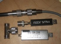
It was not until I removed the Tee next to the rigs that I was able to figure out the true issue. The silver SDR when tested with a DMM showed resistance from the center to the shield when off. The black SDR did not and was fully open when off. I had been swapping them back and fourth trying to sort out an UN-related USB cable issue.

Looking back I now think the silver SDR was causing signal attenuation, enough to completely drop the UHF repeater I was trying to pick up. But it was passing enough signal to let everything else work and make this one of those learning experiences.

Next time - start at the Tee! DOH ;-)
 

Attachments

  • TeeSDR.jpg
    TeeSDR.jpg
    133.4 KB · Views: 21

dkcorlfla

Member
Joined
Feb 12, 2023
Messages
98
Location
Orlando
Thats why the T is not the preferred method. Either a multicoupler or something like a Electroline EDA-2800 8 port splitter.
I was hoping to be able to get by with the cheap Tee but that did not work out too well. Doing it right will cost lots of money so I think for now I will just use the barrow connector as it is shown in the picture and only use the scanner or the SDR one at a time.

I did run across a post of someone using a TV splinter but those are 75 Ohms and that would kill some of the signal I tried so hard to save with the run of KLMR 400 cable.

Do it right or don't do it ;-)
 

6079smithw

Member
Joined
Jun 20, 2004
Messages
437
Location
Near the Biggest Little City
Looking back I now think the silver SDR was causing signal attenuation, enough to completely drop the UHF repeater I was trying to pick up. But it was passing enough signal to let everything else work and make this one of those learning experiences.
BTDT many times, but as you stated, it's a learning process. Like Billy Joel sang:
"The things I did not know at first, I learned by doing twice!" ("The Entertainer" 1974)
 
Last edited:

prcguy

Member
Joined
Jun 30, 2006
Messages
15,346
Location
So Cal - Richardson, TX - Tewksbury, MA
A direct conversion SDR can produce a signal on the frequency its receiving that can interfere with other receivers. A "T" adapter will not provide any isolation between receivers but a power divider will and somewhere between 20 and 30dB depending on the mfr and model.
 

Ubbe

Member
Joined
Sep 8, 2006
Messages
9,033
Location
Stockholm, Sweden
Doing it right will cost lots of money
You loose 0,2dB at each transition between 50 and 75 ohm. If you have good and strong signals for everything you receive then you can use a 1 to 2 CATV 75 ohm splitter that has 3-4dB attenuation and more than 20dB isolation between ports. There's no need to use expensive low loss coax if you only receive. Use 75 ohm RG6 and 75 ohm splitters and set a low noise amp at the antenna and it will perform much better than a LMR400 without the amp. The money you save from not using LMR400 can be spent on the amplifier and then you can also use a 1-4 splitter, or more, without loosing any signal.

There are also other advantages, that the splitter will give a constant impedans to your receivers and to the coax and the amplifier will produce a constant impedance to the antenna and to the coax. All the impedances will be stabilized and any loss due to impedance mismatch will be more than compensated for by the gain of the amplifier. Just insert a small capacitor inline, preferable inside the splitter, to EQ the gain to produce the same signal level across all frequencies. Also some way of attenuating the signal are needed as the amplifier will probably have too much gain.

/Ubbe
 
Top