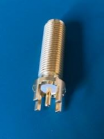
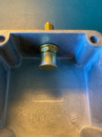
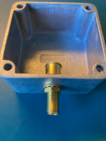
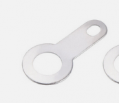
Some more information: here is the connector:

And its
datasheet. Despite being brass, the datasheet specifies a mating torque of 7-10 inch-lbs, and a mounting torque of 15 inch lbs. Probably my main problem is that I torqued the mounting nut to only 8 in-lbs, not having a 15 in-lbs wrench. But the connector was still rotating after using only 4.4 inch lbs (0.5 N m) mating torque.
Here's what I did to that connector. I carefully sawed off the pins and filed the surfaces flat. I then surface mounted two 100 ohm RF resistors in parallel between center pad and shield. I cut a short length of brass tubing that has an I.D. almost exactly that of the base of the connector, and cut a brass disk from a sheet. Using solder paste and hot air, I soldered these onto the connector to make a shield. It looks like this:


I likewise made one with no resistors (open) and another with just the brass plate soldered directly onto the back of the SMA connector. As you can guess by now, these are meant to be VNA calibration standards with consistent delays and losses. The aluminum boxes are only for mechanical support so that I don't have to use two wrenches when attaching and detaching cables.
It's bad when these start rotating in the chassis, though, because then I can't remove the cable and have to take the top off the box and hold the back with pliers, risking damage to my nice little shield..
I will try some glue on the inner nut and try to tighten it harder.


