• To anyone looking to acquire commercial radio programming software:

    Please do not make requests for copies of radio programming software which is sold (or was sold) by the manufacturer for any monetary value. All requests will be deleted and a forum infraction issued. Making a request such as this is attempting to engage in software piracy and this forum cannot be involved or associated with this activity. The same goes for any private transaction via Private Message. Even if you attempt to engage in this activity in PM's we will still enforce the forum rules. Your PM's are not private and the administration has the right to read them if there's a hint to criminal activity.

    If you are having trouble legally obtaining software please state so. We do not want any hurt feelings when your vague post is mistaken for a free request. It is YOUR responsibility to properly word your request.

    To obtain Motorola software see the Sticky in the Motorola forum.

    The various other vendors often permit their dealers to sell the software online (i.e., Kenwood). Please use Google or some other search engine to find a dealer that sells the software. Typically each series or individual radio requires its own software package. Often the Kenwood software is less than $100 so don't be a cheapskate; just purchase it.

    For M/A Com/Harris/GE, etc: there are two software packages that program all current and past radios. One package is for conventional programming and the other for trunked programming. The trunked package is in upwards of $2,500. The conventional package is more reasonable though is still several hundred dollars. The benefit is you do not need multiple versions for each radio (unlike Motorola).

    This is a large and very visible forum. We cannot jeopardize the ability to provide the RadioReference services by allowing this activity to occur. Please respect this.

HP8920B CRT DISPLAY SHIFTED VERTICALLY HELP!!!!!!!!!

RFI-EMI-GUY

Member
Joined
Dec 22, 2013
Messages
7,711
I have an very useful, if not antique, HP8920B Comm Test set that has performed flawlessly for decades of occasional use. Today out of the blue I get a display shifted vertically to top of screen. I cannot figure out if it is a problem in the test set or the Omnivision CRT assembly. I did try the Vert Hold as it seems to be the only option and other than messing with sync, I am back at same problem. The only documentation for the CRT monitor I have is a generic Omnivision document. I am really trying to figure out where to start, the CRT or the test set. The scan rate is odd or I would hook up another monitor somehow. Thanks Joe

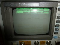
This (example) is all that I can see on my screen and it is shoved all the way to top of the screen. There is something out of whack. No distortion of the display (looks ok, maybe a bit small?) and I just discovered this today after months of the unit just sitting there. I cant see any error codes because those usually pop up at top of the screen. I reseated the controller and CRT driver in the test set to no avail. The bottom picture is what should be displayed.

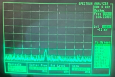
1) The problem: and 2) What it should look like:
 

Attachments

  • P1180596.JPG
    P1180596.JPG
    163 KB · Views: 25
  • 7zwpqdbw.png
    7zwpqdbw.png
    272 KB · Views: 25

RFI-EMI-GUY

Member
Joined
Dec 22, 2013
Messages
7,711
Someone suggested a capacitor "near the yoke" was leaky. could it be the yoke has some unwanted DC bias? the image is somewhat scrunched, maybe to 90% of horizontal width. yet 80% is off screen toward top. trying to figure out next steps.
 

prcguy

Member
Joined
Jun 30, 2006
Messages
17,389
Location
So Cal - Richardson, TX - Tewksbury, MA
Someone suggested a capacitor "near the yoke" was leaky. could it be the yoke has some unwanted DC bias? the image is somewhat scrunched, maybe to 90% of horizontal width. yet 80% is off screen toward top. trying to figure out next steps.
The display should be common to many other pieces of HP test equipment. Maybe do a search for the same problem with spectrum analyzers or other models. Or you should be able to pick up a CRT display module cheap from someone who upgraded to LCD.
 

RFI-EMI-GUY

Member
Joined
Dec 22, 2013
Messages
7,711
The display should be common to many other pieces of HP test equipment. Maybe do a search for the same problem with spectrum analyzers or other models. Or you should be able to pick up a CRT display module cheap from someone who upgraded to LCD.
I think I have an entire CRT module in a box somewhere. With my luck, it is probably bad as well, I don't think it was stored very well. I like to figure out the theory and possible solution before warming up a soldering iron. These units are a beast to take apart. As many fasteners and as fiddly as my Craftsman lawn tractor.
 

RFI-EMI-GUY

Member
Joined
Dec 22, 2013
Messages
7,711
The display should be common to many other pieces of HP test equipment. Maybe do a search for the same problem with spectrum analyzers or other models. Or you should be able to pick up a CRT display module cheap from someone who upgraded to LCD.
I have posted on some generic HP forums. I found the spare module in the garage. Of course it smells musty and it lacks any model specific nomenclature. The screen is burned in so maybe I can suss out the model it was in by the faded damage. I just put the monitor back together because this looks like a major project where I will gather ideas and knowledge and probably end up recapping the entire CRT module simply because it is PITA to remove it. If I get it fixed, I will change the lithium memory battery which is decades overdue. I just printed about 20 pages from the manual pertaining to all the disassembly. I will research the LCD retrofit as well. I like this unit. It came from Lynchburg at about the time they were closing down some production. It had been used in a lab and is entirely free of dust. I paid some 4 kilobucks back then for the honor.
 

MUTNAV

Active Member
Premium Subscriber
Joined
Jul 27, 2018
Messages
1,478
There is a HP-141T mod that I was thinking of doing (if my CRT ever dies, and the wieght of the 141T doesn't kill me), Maybe something like this could be used for your CRT, if not for a replacemwent, then maybe for a way to help troubleshoot the amplifier power supply voltages.


Sounds like a good project, PLEASE keep us up to date as to how it goes.

Disregard...., just found the mods done for LCD and the 8920B, very nice looking ! !

Thanks
Joel
 
Last edited:

merlin

Active Member
Joined
Jul 3, 2003
Messages
3,630
Location
DN32su
Those CRT modules are the same across a number of HP devices, My spectrum analyzer does a wig out now and then, looses horizontal. Yea, I could go the LCD rout, but a lot more expensive than $300.
So, what may have happened is you lost a glued on focusing magnet or the vertical output series capasitor has failed.
Can't rule out the vertical driver IC.
This is pretty much old school TV stuff.
BTW, no documentation for the display module, but it is the same Matsushita module in some small portable TVs.
 

RFI-EMI-GUY

Member
Joined
Dec 22, 2013
Messages
7,711
Those CRT modules are the same across a number of HP devices, My spectrum analyzer does a wig out now and then, looses horizontal. Yea, I could go the LCD rout, but a lot more expensive than $300.
So, what may have happened is you lost a glued on focusing magnet or the vertical output series capasitor has failed.
Can't rule out the vertical driver IC.
This is pretty much old school TV stuff.
BTW, no documentation for the display module, but it is the same Matsushita module in some small portable TVs.
I had considered the unit needed degaussing . As we did have some insane lightning the other day. . The fact that the portion that remains on screen is so very symmetrical and does not roll over to the bottom suggests it is the DC block capacitor feeding the yoke, not a synch problem. It is indeed old school TV tech.
 

AK9R

Lead Wiki Manager and almost an Awesome Moderator
Staff member
Super Moderator
Joined
Jul 18, 2004
Messages
10,496
Location
Central Indiana

RFI-EMI-GUY

Member
Joined
Dec 22, 2013
Messages
7,711
I've been told this works on the 8920:
Yeah that is my plan B. I will be taking the unit apart once again to get inside the CRT assembly. I am pretty sure it is the leaky V yoke coupling cap, at least that is what my logical thinking is. If so, I will probably recap the other parts of the CRT unit. I have never been a fan of totally recapping stuff, but getting at and into the CRT can is laborious. If I muff that, it will be an LCD upgrade. Also other deferred maintenance like finally changing the memory board lithium battery. Just removing the outer instrument case is a PITA as it is very tight, metal on metal.
 

ElroyJetson

Getting tired of all the stupidity.
Premium Subscriber
Joined
Sep 8, 2002
Messages
3,970
Location
Somewhere between the Scylla and Charybdis
A capacitor in the vertical amp section of the circuit has gone leaky. The resulting DC offset is responsible for the changed position of the raster, upwards. it's probably a two dollar part and if you can find the display's service documentation, you can narrow it down to one of just a few possible parts.
It'd be worth just replacing all electrolytics in the CRT assembly with new ones of the same original specs, only with higher rated operating/temp specs if possible.
 

RFI-EMI-GUY

Member
Joined
Dec 22, 2013
Messages
7,711
A capacitor in the vertical amp section of the circuit has gone leaky. The resulting DC offset is responsible for the changed position of the raster, upwards. it's probably a two dollar part and if you can find the display's service documentation, you can narrow it down to one of just a few possible parts.
It'd be worth just replacing all electrolytics in the CRT assembly with new ones of the same original specs, only with higher rated operating/temp specs if possible.
Yeah; I have to clear some space on the bench this week and tear it apart to get the CRT module out. There are several maker versions of this CRT assembly, all different vertical circuit designs. I have a bunch of new capacitors in the range, but they are off brand stuff, best used to test my hypothesis. The available manuals for the possible modules give values but not physical size or temperature ratings. So I will have to take it apart, change the suspect capacitor, measure other capacitors in circuit, generate a bill of materials (Panasonic caps, Digikey), put it together enough to test with the suspect capacitor installed, place order with DigiKey and repeat the process. The hard part is getting the outer shell off the instrument, it is very tight and makes annoying scraping sounds coming off and going on.
 
Top