KC9LQV
Member
I have an Icom IC-2720 with an OPC-1155 separation cable that got flakey. The plug at the chassis end would cause the radio to power off if disturbed. Swapping out the cable eliminated the problem, so I know it's not the plug on the chassis.
I have the 6P6C plugs and crimping tool, and have cut the bad plug off and taken a peek at the conductors.
I have one question, though. The red (pin 5) and white (pin 4) wires are shielded by strands. What I can't tell for sure is what to do with those shields at the plug. Are they being twisted together and used as the conductor at pin 3?
I've tried to scrutinize the original plug carefully, but my crappy eyesight doesn't help. There appears to be a conductor in pin 3, but that's one more wire than used in the cable unless you count the shield.
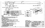
I'm attaching the schematic for the cable. Please take a look at it, as I'm not sure how to interpret the pinout. It shows pin 3 "connecting" to both pin 4 and 5. If someone could clarify it would be great.
Hope the schematic helps anyone else who wants to repair or fabricate a separation cable.
I have the 6P6C plugs and crimping tool, and have cut the bad plug off and taken a peek at the conductors.
I have one question, though. The red (pin 5) and white (pin 4) wires are shielded by strands. What I can't tell for sure is what to do with those shields at the plug. Are they being twisted together and used as the conductor at pin 3?
I've tried to scrutinize the original plug carefully, but my crappy eyesight doesn't help. There appears to be a conductor in pin 3, but that's one more wire than used in the cable unless you count the shield.
I'm attaching the schematic for the cable. Please take a look at it, as I'm not sure how to interpret the pinout. It shows pin 3 "connecting" to both pin 4 and 5. If someone could clarify it would be great.
Hope the schematic helps anyone else who wants to repair or fabricate a separation cable.