Information needed with multiple stacked yagi's

VA3BBY

Member
Joined
Mar 29, 2023
Messages
45
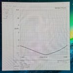
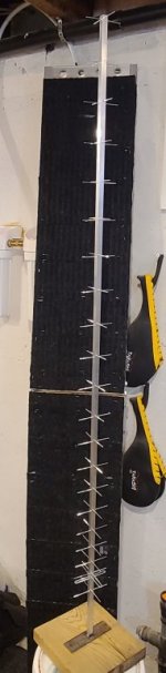
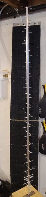
Hello from Northwestern Ontario Canada, I am hoping someone here can help me with a Yagi Antenna Array. I have used K7MEM’s calculator for the individual antennas being 23 element @ 1440mhz with an estimated 15.9db gain and 24 degree beam width.

These antennae will be utilized for radio astronomy in a 3 x 3 antenna array pattern omitting the centre antenna only because I can not locate any information on how to phase 9 antennas together with coax. My thoughts are that a square shape pattern would provide a more circular beam and for me more mechanically adaptable vs a rectangular shape. Like wind load leverage.

All I have been able to find is multiples of 2 or 4 for joining antennas together. So at this point I only have information to connect 8 antennas unless someone can help with adding #9 which would be super great because I have material for 9. I do not want to get into expensive off the shelf antenna combiners.

I am also looking for information of beam width and gain for stacking multiple antennas together. There is much information on putting 2 yagi’s together but nothing beyond that unless you have a major in electrical engineering to decipher the formulas. I am just looking for a rule of thumb based on my antenna mentioned above and the number of antenna I want to put into the array.

Information I have found on stacking two yagi antennas together loosely claim 2x db gain (3db) and 1/2 the beam width. But beyond stacking 2 together I have found nothing.

I need the estimated beam width so I can input the data into a radio astronomy program I am running so that it can show a real-time observation (receiving) with the Meridian Drift Scan Table. Once inputted the beam pattern is projected onto the realtime display.

These antenna are of cross polarization design with 2 coax coming from the array to the receiver so left circular, right circular, horizontal or vertical polarization can be achieved.

Thank you,

Bob
 

Token

Member
Joined
Jun 18, 2010
Messages
2,382
Location
Mojave Desert, California, USA
I am just looking for a rule of thumb based on my antenna mentioned above and the number of antenna I want to put into the array.

Information I have found on stacking two yagi antennas together loosely claim 2x db gain (3db) and 1/2 the beam width. But beyond stacking 2 together I have found nothing.

I need the estimated beam width so I can input the data into a radio astronomy program I am running so that it can show a real-time observation (receiving) with the Meridian Drift Scan Table. Once inputted the beam pattern is projected onto the realtime display.

These antenna are of cross polarization design with 2 coax coming from the array to the receiver so left circular, right circular, horizontal or vertical polarization can be achieved.

Using rules of thumb in cases like this can be misleading. The correct answer is to actually model things. When you use rules of thumb you are almost always using wrong numbers, and they should only be used as an idea of your approximate nominal performance. With that statement on the inaccuracy of such an approach, some rough rules of thumb below, for antennas in free space (does not account for things like ground gain).

The gain from stacking 2 antennas is a bit less than 3 dB. In a perfect world it would be 3 dB of gain, but in addition to halving the beamwidth (giving you 3 dB of gain) you also introduce grating lobes (taking some energy away from the forward gain), so it is somewhat less. In theory it is about 2.85 dB or so, in application, after matching section losses and such, it can be more like 2.5 - 2.8 dB (~2.85 dB max). And this is the same as you add on, every time you double the count you gain about 2.5 - 2.8 dB. 4 antennas is about 5 - 5.6 dB (~5.7 dB max) more than a single, and 8 is about 7.5 - 8.4 dB (~8.55 dB max) more than a single.

Beamwidth does about the same, halving for ~ 2.85 dB gain, but only in the plane of the added antennas. Two antennas, one stacked above the other, will result in a beamwidth of about half of the single antenna in the vertical axis, and about the same as the single antenna in the horizontal axis. While 2 antennas stacked side by side, horizontally, will result in a beamwidth of about half of a single antenna beamwidth in the horizontal plane, and about the same as the single antenna in the vertical plane. 4 antennas in an H or box array will result in half the beamwidth of a single antenna in both the horizontal and vertical axis.

Your 8 antennas in a 3 x 3 array with center missing, is going to have less than optimal gain and beamwidth because of that missing center antenna. It will change the element spacing as the boom to boom relationship of the antennas across the hole in the middle of the array will be different than the boom to boom relationships of any adjacent Yagi pair.

However, just eyeballling it, assuming your beamwidth for your single antenna is correct, and using rules of thumb, you are probably looking at a 3 dB beamwidth of about 8 - 10 degrees, in both E and H planes.

Also, your intent is to do the polarization selection by introduction of the hybrid at the receiver end vs at the array? Are you confident of the phase relationship of your feedlines? Not just that they are the same phase length, but also that they are the same number of wavelengths long (same total length)? I have generally had better luck with polarization switching at the array. And also you have half the feedline run, so half the potential headaches and expense associated with the feedlines (at the cost of the greater expense and complexity of the remote polarization switching).

T!
 
Last edited:

MUTNAV

Active Member
Premium Subscriber
Joined
Jul 27, 2018
Messages
1,092
Using rules of thumb in cases like this can be misleading. The correct answer is to actually model things. When you use rules of thumb you are almost always using wrong numbers, and they should only be used as an idea of your approximate nominal performance. With that statement on the inaccuracy of such an approach, some rough rules of thumb below, for antennas in free space (does not account for things like ground gain).

The gain from stacking 2 antennas is a bit less than 3 dB. In a perfect world it would be 3 dB of gain, but in addition to halving the beamwidth (giving you 3 dB of gain) you also introduce grating lobes (taking some energy away from the forward gain), so it is somewhat less. In theory it is about 2.85 dB or so, in application, after matching section losses and such, it can be more like 2.5 - 2.8 dB (~2.85 dB max). And this is the same as you add on, every time you double the count you gain about 2.5 - 2.8 dB. 4 antennas is about 5 - 5.6 dB (~5.7 dB max) more than a single, and 8 is about 7.5 - 8.4 dB (~8.55 dB max) more than a single.

Beamwidth does about the same, halving for ~ 2.85 dB gain, but only in the plane of the added antennas. Two antennas, one stacked above the other, will result in a beamwidth of about half of the single antenna in the vertical axis, and about the same as the single antenna in the horizontal axis. While 2 antennas stacked side by side, horizontally, will result in a beamwidth of about half of a single antenna beamwidth in the horizontal plane, and about the same as the single antenna in the vertical plane. 4 antennas in an H or box array will result in half the beamwidth of a single antenna in both the horizontal and vertical axis.

Your 8 antennas in a 3 x 3 array with center missing, is going to have less than optimal gain and beamwidth because of that missing center antenna. It will change the element spacing as the boom to boom relationship of the antennas across the hole in the middle of the array will be different than the boom to boom relationships of any adjacent Yagi pair.

However, just eyeballling it and using rules of thumb, you are probably looking at a 3 dB beamwidth of about 8 - 10 degrees, in both E and H planes.

Also, your intent is to do the polarization selection by introduction of the hybrid at the receiver end vs at the array? Are you confident of the phase relationship of your feedlines? Not just that they are the same phase length, but also that they are the same number of wavelengths long (same total length)? I have generally had better luck with polarization switching at the array. And also you have half the feedline run, so half the potential headaches and expense associated with the feedlines (at the cost of the greater expense and complexity of the remote polarization switching).

T!
Regarding the phase relationships of the feed-line, a poorly characterized part of it is temperature stability.

In an expensive (both money and time) but very valuable experience, A glideslopes feed lines were done with RG-214, thinking that it would offer superior performance to the normal RG-213 used, at about 330 MHz, the temperature changes between night and day caused the phasing to be significantly off. A 6" section was left outside of the equipment shelter for 15 minutes, and it showed a 3+ degree difference in phase as measured with a vector voltmeter.

ALSO understand that if you use something like an N type connector, how far you screw the connector on to its mate, you will change the phasing at 1440 MHz...


It may be worth reconsidering the enterprise, a dish with a helical feed would take care of most of your problems.

Thanks
Joel
 

Token

Member
Joined
Jun 18, 2010
Messages
2,382
Location
Mojave Desert, California, USA
Regarding the phase relationships of the feed-line, a poorly characterized part of it is temperature stability.

<<<snip>>>

It may be worth reconsidering the enterprise, a dish with a helical feed would take care of most of your problems.

Yeah, that temp issue was what I had in mind. I have been bitten in the butt by that many times before. An example would be a monopulse radar, where there was no attempt by the designer to insure total length of the 3 IF lines (Sum, AZ, and EL) were identical, rather they just used mechanically convenient lengths and then a phase adjuster to align the phaselengths. In theory this works fine, and did work at the time of adjustment. But over the day, as temperatures changed, the fact that the 3 IF lines were not acutally matched resulted in significantly differnet phase shift with heating and cooling.

Also agree on the dish thing. Talking about a performance point of ~ 8 degree beamwidth (to roughly equal the Yagi array, or a little better), at 1440 MHz and assuming 60% efficiency of the feed that is about a 6 foot dish. I don't think an 8 Yagi array will be mechanically any simpler than that.

T!
 

MUTNAV

Active Member
Premium Subscriber
Joined
Jul 27, 2018
Messages
1,092
I'm surprised no one seems to have done anything comparing phase stability with coaxs under different conditions, bends, temperature etc...

Thanks
Joel
 

MUTNAV

Active Member
Premium Subscriber
Joined
Jul 27, 2018
Messages
1,092
A helix feed, especially one intended for wider frequency ranges, is also more forgiving of construction tolerances.

Thanks
Joel
 

VA3BBY

Member
Joined
Mar 29, 2023
Messages
45
First I would like to thank you folks for taking the time to reply with your suggestions.

Largely due to frustration, I installed EZNEC PRO/2 V 7.0 this morning and have since abandoned the yagi design I mentioned above for various reasons. I spent several hours on a 23 element today which is just over 7 wavelengths long. I am happy with the less than 1.5swr over 25mhz either side of the design frequency at 50ohms and almost 1:1 at design.

Now if I can just keep a less than 1/64th of an inch tolerance, I will be all set…. that’s .4mm for us folks up north. It wasn’t to hard to adapt, get the hang of this EZNEC program, I have spent over 30 years working with ACad so it was reasonably intuitive for me. The wire table is based on the xyz coordinate system.

What I am surprised about, is the lack of tutorials available for the basic old school stuff like folded dipole driven elements for a yagi, or a balanced t-match as opposed to gamma or step by step instructions on phasing multiple antennas together and making simple 4:1 baluns. Just try and look for some of this stuff on the internet. Seems everybody wants to show they can design a torqued out bingle rotor for the domahicky twister radiator these days… Anyways,

I have decided to go with this single polarization and 12 antennas in an array. I have not decided on polarization yet as it will be 20 dregees to zenith so not sure which will give best side rejection.

The comment about the centre antenna missing on a 9 position array made sense to me as well as the comments about coax, and with cross polarization there would have been a lot of it. Although I appreciate the suggestions of the dish and have thought of it, and it would be cool. It is just not practical for me on many aspects. Especially since I am mounting this on my unused chimney, a dish would look like the Parkes telescope sitting on a thimble.

Besides I will be picking up the boom material this weekend as it has arrived from Winnipeg. Spacing on the antennas of this is only 450mm I am pretty sure this is center boom to center boom but not 100% yet, and there is lots of free space for wind to pass through.

If anyone has further suggestion about what I am building, they would be very much appreciated.

I don’t know if it is common knowledge but EZNEC Pro/2 is now free to download from their website as the developer has retired. So if you are into a bit of head scratching at the start and don’t mind going beyond 2 dimensional thinking…. You couldn’t go wrong with this generous offer. I certainly appreciated it.

Thanks again,

Bob
 

VA3BBY

Member
Joined
Mar 29, 2023
Messages
45
Heres a picture of todays effort.
 

Attachments

  • 20230330_201905 (002).jpg
    20230330_201905 (002).jpg
    176 KB · Views: 16

MUTNAV

Active Member
Premium Subscriber
Joined
Jul 27, 2018
Messages
1,092
First I would like to thank you folks for taking the time to reply with your suggestions.

Largely due to frustration, I installed EZNEC PRO/2 V 7.0 this morning and have since abandoned the yagi design I mentioned above for various reasons. I spent several hours on a 23 element today which is just over 7 wavelengths long. I am happy with the less than 1.5swr over 25mhz either side of the design frequency at 50ohms and almost 1:1 at design.

Now if I can just keep a less than 1/64th of an inch tolerance, I will be all set…. that’s .4mm for us folks up north. It wasn’t to hard to adapt, get the hang of this EZNEC program, I have spent over 30 years working with ACad so it was reasonably intuitive for me. The wire table is based on the xyz coordinate system.

What I am surprised about, is the lack of tutorials available for the basic old school stuff like folded dipole driven elements for a yagi, or a balanced t-match as opposed to gamma or step by step instructions on phasing multiple antennas together and making simple 4:1 baluns. Just try and look for some of this stuff on the internet. Seems everybody wants to show they can design a torqued out bingle rotor for the domahicky twister radiator these days… Anyways,

I have decided to go with this single polarization and 12 antennas in an array. I have not decided on polarization yet as it will be 20 dregees to zenith so not sure which will give best side rejection.

The comment about the centre antenna missing on a 9 position array made sense to me as well as the comments about coax, and with cross polarization there would have been a lot of it. Although I appreciate the suggestions of the dish and have thought of it, and it would be cool. It is just not practical for me on many aspects. Especially since I am mounting this on my unused chimney, a dish would look like the Parkes telescope sitting on a thimble.

Besides I will be picking up the boom material this weekend as it has arrived from Winnipeg. Spacing on the antennas of this is only 450mm I am pretty sure this is center boom to center boom but not 100% yet, and there is lots of free space for wind to pass through.

If anyone has further suggestion about what I am building, they would be very much appreciated.

I don’t know if it is common knowledge but EZNEC Pro/2 is now free to download from their website as the developer has retired. So if you are into a bit of head scratching at the start and don’t mind going beyond 2 dimensional thinking…. You couldn’t go wrong with this generous offer. I certainly appreciated it.

Thanks again,

Bob
I'm still not entirely sure why combining 9 antennas is more difficult, do they (you know "those guys") not make (or can you not make) 9 port combiners?

Also, how were you going to do the polarization? I was thinking about it last night before sleep, and crossed yagis and a phasing stub (at the antenna elements) seem to have been the popular* arrangement.

* (popular in the loose sense)

Thanks
Joel
 

VA3BBY

Member
Joined
Mar 29, 2023
Messages
45
I think those guys by rule of thumb, just like to keep that stuff secret. I read somewhere on here the term voodoo or magic.

As for your phasing question, It was a simple coax circuit described by PA3GUO which had 3 female terminals, I was going to use SMA. Depending on the way (combination) you screwed in the 2 antenna feeds and receiver line you could obtain any of the 4 states of polarization I mentioned in my first message.

The more I research this, I think it has something to do with maintaining equal lengths of coax for each antenna in the phasing process and with the odd antenna, it can not be achieved. Or so I loosely think so.....
 

VA3BBY

Member
Joined
Mar 29, 2023
Messages
45
Mutnav, I have decided to pursue the 9 bay array. I have not figured out how to do it yet, but I will. To me this array is like art, not just something round like a soup bowl... In fact, I am going to hang the first yagi (as mentioned later) for this frequency from my living room ceiling just as such : ) maybe weird to some,

So, I have spent some time since my original post and have come up with a few ideas. Maybe some things to look out for if anyone else is looking into radio astronomy.

First, it is critical that you have the equipment to follow the exacting measurements required, less than .5mm tolerance is marginally acceptable. I think that equates to 1/64 of an inch. I am talking 1mm length difference between elements. And second, there is not too much information on design of these antennas to be had, probably because of the tolerances, (I'm sure you could cram a wet aspen stick into an HF antenna and it would work). And third, take any online design programs with a grain of salt before you spend any money and verify the output.

I have spent countless hours with a design program and compared many online antenna formulas. In these upper frequencies, element diameter plays a huge factor on performance to the point where the elements become so small that they are impractical to build in the real world. I have built two antennas recently that I will share with you. I am no stranger to AutoCad, have been using it for 30 plus years, so I am well aware of tolerance.

Ultimately what I have come to realize, is that tweaking element spacing is actually not worth the effort to gain the extra .5 to 1 dBi gain. Why, because it becomes impractical to build and I will show you this as well in an example. I am sure it is cool to say I have and antenna design that has 18dB gain plus, but just try to build the darn thing especially in a cross polarized configuration.

I have gone back to my original cross polarization idea(post), because if I didn't, it would be a regret down the road. Besides, I am up for the challenge, and yes, I am confident I can use a ruler to measure coax accurately for phasing.

At the risk of using the term "rule of thumb again" this is what I have gone back to in antenna design. With the exception of the reflector, driven and first radiator I have gone back to the tried and true .4 wave length spacing with remarkable results plus ease of construction and it is 1/4 wave offset friendly.

I have included a couple of pictures. The first antenna I built was per a template and rescaled to my design frequency and a few tweak's . It was optimised for gain. But as you can see, it is impractical to connect coax to the driven elements, I would have to loop forward with the coax on the front driven element to make the connection. This would be compounded by the restraints of phasing harness coax lengths. The only way this optimised yagi can be crossed polarized is by placing the elements adjacent as I built. The elements can not be separated by the "rule of thumb" 1/4 wave as the elements would overlap with each (land on top) of each other because of the optimised spacing for gain. Also, drilling for the required 1/16" elements was arduous. You need very high speed and lots of coolant to drill a hole at 1/16" accurately, this is way beyond the capabilities of a standard drill press. I think I spent more time reaming the holes after they were drilled just so they would accept the element rods, that in itself is not accurate.

Also I include a picture of a template I made so each of the booms could be drilled Identical, as well as a jig to form all the dipoles exactly the same as they pass through boom and are bonded. It is imperative that all segments of an antenna array be the same. The downside is it would be 9 equal mistakes if things didn't work out as planned.. lol

My second antenna attempt, utilizes the rule of thumb .4 wave spacing but sacrifices almost a full 1 dB gain on an 9 bay array ( 27 vs 28dBi) which I do not think is here nor there considering how much more practical or realistic this is to build. This second antenna is all 2.4mm (3/32) elements, which again is not friendly to optimized designs. I do not have the equipment to accurately drill holes at this as well, but with lots of patience and coolant it can be done reasonable well with a regular drill press. When you are dealing with cutting and drilling 400 elements for an array, this does make a difference. This is a bonded design and is another conundrum with a multitude of formulas for BC (boom correction) in my case for a 12.7mm (1/2") boom I went with 7mm.

Sure would have been nice if someone on here would have said ("hey this is what works....)

Something I did come across of interest was a copy of chapter one of "Receiving Antennas are Different" (www.arrl.org/shop/files/pdfs/Rec%20Ant%20Chap%201.pdf) It was one of my earlier unanswered questions here. It would be nice to read the full article but not going to spend that much money on a book for one segment. I think someone else on this forum has been saying the likes of this chapter ("its a receiving antenna it doesn't matter') to no avail, but nobody is listening...

I am not really looking for advice anymore, because I don't think it is here on this forum, for this topic or frequency anyway, but rather offering some pointers because of the lack of aforementioned information and what I have learned since my original post.

All I am interested in is helping someone, I don't need to prove my smarts, because I don't have any.

Cheers
 

Attachments

  • 1.jpg
    1.jpg
    113.7 KB · Views: 9
  • 2.jpg
    2.jpg
    30.8 KB · Views: 9
  • 3.jpg
    3.jpg
    27.8 KB · Views: 10
Top