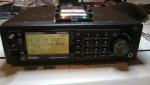
Which scanner?
You need a minimum 3-pin connection for the GPS: power, ground, and data. I've done what you are describing 2 different ways with the mobile scanners:
1. Connect +5V power to pin 9 of the DB-9 connector on the back of the scanner, then put a DB-9 connector on a Uniden or similar puck, so the puck connects directly to the scanner without the extra wiring going to the 12V plug. (Posts 2-3) This can be done with any GPS module with a RS-232 output, housing and cable, such as
https://www.amazon.com/GlobalSat-BR-355S4-GPS-Receiver-Black/dp/B00AMAJFUO or you can construct your own housing and put a module of your choice in it. There are dozens of options on Amazon and eBay for modules and housings if you want to DIY to that level. If you want to be able to easily swap modules for testing purposes, this is definitely the way to go.
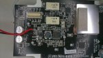
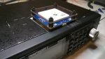
2. Get a module with 4 mounting holes, and mount it to the scanner case similar to what I did in post 32. If you get a module with status LEDs on the same side of the circuit board as the antenna, you can eliminate the need for wiring separate status LEDs.
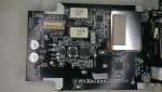
Modding a 436 to accept an external GPS powered by the scanner is possible, but not really practical. The GPS connector is buried under a metal shield soldered to the front board in several places, and removing it without specialized desoldering tools is not advisable. The GPS connector pins are also very closely spaced, and soldering one without bridging multiple pins together with solder would be very difficult.

")