• To anyone looking to acquire commercial radio programming software:

    Please do not make requests for copies of radio programming software which is sold (or was sold) by the manufacturer for any monetary value. All requests will be deleted and a forum infraction issued. Making a request such as this is attempting to engage in software piracy and this forum cannot be involved or associated with this activity. The same goes for any private transaction via Private Message. Even if you attempt to engage in this activity in PM's we will still enforce the forum rules. Your PM's are not private and the administration has the right to read them if there's a hint to criminal activity.

    If you are having trouble legally obtaining software please state so. We do not want any hurt feelings when your vague post is mistaken for a free request. It is YOUR responsibility to properly word your request.

    To obtain Motorola software see the Sticky in the Motorola forum.

    The various other vendors often permit their dealers to sell the software online (i.e., Kenwood). Please use Google or some other search engine to find a dealer that sells the software. Typically each series or individual radio requires its own software package. Often the Kenwood software is less than $100 so don't be a cheapskate; just purchase it.

    For M/A Com/Harris/GE, etc: there are two software packages that program all current and past radios. One package is for conventional programming and the other for trunked programming. The trunked package is in upwards of $2,500. The conventional package is more reasonable though is still several hundred dollars. The benefit is you do not need multiple versions for each radio (unlike Motorola).

    This is a large and very visible forum. We cannot jeopardize the ability to provide the RadioReference services by allowing this activity to occur. Please respect this.

Johnson Messenger 223 low sensitivity

sas73

Member
Joined
Jan 26, 2016
Messages
7
Hello guys,
I got a problem with an J. Messenger 223 23ch. CB radio - low sensitivity on all channels.
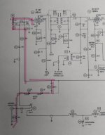
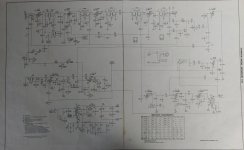
Measured with my RF generator: at -73dbm I can barely hear a signal, and that after alignment of IF 455KHZ coils and input RF coils Tested switchover relay (K1) , and D4, D5 (X4, X5). Measured resistance at V1 between PIN1 and a GROUND 120K, according to SM should be 21K.
I know it's hard to troubleshoot remotely, but any help will be really appreciated.

Thanks!msg223_02.jpeg
 

sas73

Member
Joined
Jan 26, 2016
Messages
7
I understand , this is my friend first radio (emotional and nostalgic value) .
Electrolytics capacitors been replaced.
 

sas73

Member
Joined
Jan 26, 2016
Messages
7
No Sir,
Unfortunately I don't have one, I usually work on solid state equipment, tube equipment is new to me.
 

prcguy

Member
Premium Subscriber
Joined
Jun 30, 2006
Messages
15,995
Location
So Cal - Richardson, TX - Tewksbury, MA
Have you tested all the Tubes with a good known Tube Tester?
Tubes and check voltages listed in the diagram. Don't overlook the local oscillators, their drive level and if everything is close enough on frequency. If the radio has drifted many KHz over the years it may be receiving ok but just way off frequency.
 

sas73

Member
Joined
Jan 26, 2016
Messages
7
DC voltages looks ok, tested local osc, frequencies is OK, need to check local osc. level.
What I don`t understand : Service manual states that on V1 pin1 to ground should be 21k , I measured 120k.
Looking at schematic, how it's even possible to have 21k ?
 

Attachments

  • 20240914_114744.jpg
    20240914_114744.jpg
    61.2 KB · Views: 10

prcguy

Member
Premium Subscriber
Joined
Jun 30, 2006
Messages
15,995
Location
So Cal - Richardson, TX - Tewksbury, MA
DC voltages looks ok, tested local osc, frequencies is OK, need to check local osc. level.
What I don`t understand : Service manual states that on V1 pin1 to ground should be 21k , I measured 120k.
Looking at schematic, how it's even possible to have 21k ?
R13 connects to stuff off to the right of R12 so there may be other paths to ground or other circuits. You might check the value of R13 and continuity back through coil A9.
 

sas73

Member
Joined
Jan 26, 2016
Messages
7
Yes, I checked values of R12 and R13, all correct, coil A9 is good, and react on adjustment (peak)
V1 and V3 has incorrect pin1 to ground resistance (120K instead of 21k) V2 has correct value of 22k.
Here is the full schematic diagram
 

Attachments

  • 20240914_125449.jpg
    20240914_125449.jpg
    104 KB · Views: 3

sas73

Member
Joined
Jan 26, 2016
Messages
7
No Sir,
Unfortunately I don`t own a tube tester , this is my first time working on tube electronic equipment
 

N1EXA

FT8 Huntin Mudd Duck on the deep end of the pond !
Joined
Mar 3, 2022
Messages
253
Location
Acushnet Heights New Bedford MA - GRID FN41 mp
Just my 2 Cents but your not using a Tube Voltmeter with High impedance and your using some digital readout portable your using the wrong meter to work on tube equipment.
Next - seeing your on frequency and everything is just weak replace the SBJ6 RF amp Tube (V1) First and see if the Radio Wakes Up !

I have fixed many Browning Golden Eagles by just replacing the RF amp Tube right off the Antenna !

s-l1600.webp


images


Pete
N1EXA
 
Last edited:

prcguy

Member
Premium Subscriber
Joined
Jun 30, 2006
Messages
15,995
Location
So Cal - Richardson, TX - Tewksbury, MA
Just my 2 Cents but your not using a Tube Voltmeter with High impedance and your using some digital readout portable your using the wrong meter to work on tube equipment.
Next - seeing your on frequency and everything is just weak replace the SBJ6 RF amp Tube (V1) First and see if the Radio Wakes Up !

I have fixed many Browning Golden Eagles by just replacing the RF amp Tube right off the Antenna !

s-l1600.webp


images


Pete
N1EXA
I think he's just measuring DC voltages around the tube, no need for an RF probe for that. Any modern DVM is plenty high impedance for measuring AC/DC voltages in a tube circuit.
 

N1EXA

FT8 Huntin Mudd Duck on the deep end of the pond !
Joined
Mar 3, 2022
Messages
253
Location
Acushnet Heights New Bedford MA - GRID FN41 mp
I was thinking that if he's using an RF generator he could look at V1 and see if there is any Amplification before its point of being
Mixed and being Demod. Thats where the RF probe and a Tube Voltmeter would help.
Id do A new V1 before any big thinking is applied to the probem !

Pete N1EXA
 
Top