Learned something new today.

Status
Not open for further replies.

KQ4BX

Member
Premium Subscriber
Joined
Jun 4, 2012
Messages
129
Location
Jensen Beach, FL
I took my HF gear apart to put it back in a better fashion. The reason was that I installed a new LDG 1000 Pro auto-tuner and also hooked up my Ameritron amp, which I had not used in a very long time.
When I was tuning the amp I would cause the radio to do a power reset. I then looked at the mess I created with all the wire and decided that I was getting stray Rf into the equipment.
So now I put everything really close together, and shortened all ground leads, looped and installed ferrite onto all coax leads, and misc control, and keyer cables.

So I get it all done and have my amp off, and in bypas, and hit my tune button on 40 meters. The radio does a power reset, WTF? So look for obvious mistakes, or any possible cause for this.
Problem solved, so it appears that I did not know that my amplifier is in circuit even in bypass, and with the power off. How did I come to that conclusion you ask? The amplifier band select was set to 15 meters, and the radio was on 40 meters. Once I turned the band selector on the amplifier to 40m, the tune button tuned with no problem, and the radio did not reset itself.

I guess it's time to look at the schematic for the amplifier to find out my bypass is not truly bypass.

Any constructive comments are welcome.

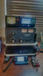
In the picture there is the Ameritron AL-811HD, Icom IC-7100, LDG 1000Pro II Auto Tuner with optional Power/SWR meter to the top right, The Daiwa CN801V UHF/VHF SWR meter to the left, and a Vibroplex signgle paddle iambic key. The radio microphone is the HM-151 and it was an option for the 7100, but came standard with the 7000. I get fantastic audio reports on the 151, and they are unsolicited, and I got more than a few, so I know it's true.
Joe
 

Attachments

  • IMG_20141220_161855231_HDR.jpg
    IMG_20141220_161855231_HDR.jpg
    52.2 KB · Views: 1,198

W3DMV

Member
Joined
Jan 2, 2009
Messages
683
Location
Gettysburg, Pa
Please, please be very careful if you remove the amplifier case and look
around. The Ameritron has lethal voltage inside. There is a bleeder resistor
that is designed to bleed the high voltage to zero when turned off but if it has
failed, the capacitors will still be charged.

Before removing the amp case:

With the amp disconnected, remove the input and output cables from
the amp and using a ohm meter measure with one probe contacting
the center pin of the input connector, and the other probe contacting the
output connector center pin. If the reading is more than a few ohms, then
the relay contacts inside the amp are stuck in the transmit condition.
Also remove the control line between the rig and the amp which controls the
relay in the amp. perhaps the control voltage from the rig is present under
all conditions and keeping the transfer relay energized..
Good luck and please be very careful !

Note: I have 3 ameritron amps and with the switch in standby condition, the transfer
relay is de-energized and the path is straight through to the antenna...

Good luck
 

dksac2

Member
Joined
Apr 18, 2012
Messages
327
Location
Idaho
It does sound like a problem in the amplifier. I have a AL-811, LDG 600PROII tuner and Yaesu radio and have had zero problems. If the band set switch is causing problems, you have a stuck relay.
John
 

KQ4BX

Member
Premium Subscriber
Joined
Jun 4, 2012
Messages
129
Location
Jensen Beach, FL
Thanks all, it might have been a stuck relay. When I tried to duplicate it, I could not get it to happen again.

Now I off to search the forum, an possibly start a new subject. I can't get communication between the 7100 and Hamradio Deluxe to work.
 

waynedc

Member
Premium Subscriber
Joined
Jan 12, 2003
Messages
146
Location
Vail, Arizona
I had the exact same issue with an Icom IC-7100 but with different accessories. For me the issue was the power supply. It was not supplying enough total amps for the tuning of the radio. The radio alone requires at least 22 amps at max transmit. I changed from a 20 amp supply to a 35 amp supply and have not had any more issues.

Wayne
N7ZQS
 

KQ4BX

Member
Premium Subscriber
Joined
Jun 4, 2012
Messages
129
Location
Jensen Beach, FL
I use a 30 amp standard analog supply.

I did get it all to work last night. The part that had to change was in the radio programming, and the CIV code changed to 88. After a few of the radio's setting were changed, the program went into full operation. I started a QRZ XML subscription , and Eqsl, and tonight I will configure DX-summit.
 

AC2OY

Member
Joined
Mar 29, 2011
Messages
2,394
Location
Belleville,New Jersey
Very nice setup! I wish I could see your antenna. I'm wanting a HF setup myself and always looking for ideas to toss around in my head.
 

KQ4BX

Member
Premium Subscriber
Joined
Jun 4, 2012
Messages
129
Location
Jensen Beach, FL
I was born in your town, and moved to Long Branch in the 3rd or 4rth grade. Use to live on 64 Forest Street. I still have contact with a neighbor from Forest Street. I live in Florida for now.

The antenna is simple, it is and Off Center fed dipole that I made myslf. I used a Balun Designs 4:1 current balun that they make for the OCD. They make a lot of baluns, but this one is duel core and rated to handle 5kw.

The CDD starts with 90x45 feet of wire, 90 on the long side, and the balun is marked for the long side, and 45 on the short. It is best to make it a little longer and use an antenna Analyzer to tune it once you get it into place.
My OCD is in an inverted V, mostly because that is all I can do with what I have. It works really well.

I can work most bands, and the antenna is resonant in 5 bands. The tuner helps keep it flat from one end of the bands to the other.
 

KQ4BX

Member
Premium Subscriber
Joined
Jun 4, 2012
Messages
129
Location
Jensen Beach, FL
I took my OCD down today and set it up as a standard OCD. 90x45. It is working well, and I have yet to see the radio do a reset. I will use more of the bands and test them from one end to the other. I used my Array Solutions Antenna Analyzer to get a graph of each band. I will try to post them here, but I don't know if there will be a limit to the number of jpg I can attach. Maybe I will post them in two messages if I have to. This will give some an idea of how well and Off Center Fed dipole can work. I have not done anymore tuning, it got too dark.
 

Attachments

  • 6m.jpg
    6m.jpg
    49.5 KB · Views: 640
  • 10m.jpg
    10m.jpg
    50.5 KB · Views: 591
  • 12m.jpg
    12m.jpg
    55.2 KB · Views: 621
  • 17M.jpg
    17M.jpg
    50.9 KB · Views: 625
  • 20m.jpg
    20m.jpg
    42.9 KB · Views: 596

KQ4BX

Member
Premium Subscriber
Joined
Jun 4, 2012
Messages
129
Location
Jensen Beach, FL
Here are the others from the same antenna. And yes, I scanned it for 2m too. It appears that I could use it if I needed to.
 

Attachments

  • 40m.jpg
    40m.jpg
    48.7 KB · Views: 592
  • 80m.jpg
    80m.jpg
    52.4 KB · Views: 592
  • 2m-WTF.jpg
    2m-WTF.jpg
    48.4 KB · Views: 619

KQ4BX

Member
Premium Subscriber
Joined
Jun 4, 2012
Messages
129
Location
Jensen Beach, FL
I found a problem with my AIM4170 made by Array Solutions. It had a bad solder joint on the S0-239 into the meter. It apparently through my readings off on the scan of my OCFD. In an effort to not post all those JPG files again, and the lack of the ability to delete them before posting the updated scans, i have tried to post a link to my dropbox where the scans can be seen in jpg format.

I m going to post the link here, and if it does not work, would a site admin please delete this so i can try again?

https://www.dropbox.com/sh/ghylmzcg4iaz6xe/AAAa6gdn1WyuuYmcmiCPEUVJa?dl=0
 
Status
Not open for further replies.
Top