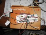
Can anyone tell me if the components are critical in value on this data slicer? I couldn't find, nor do I believe that the values on some of the resistors are even available.
Thanks.
Thanks.

 I also could have incorrectly grounded the circuit perhaps? Again, any help would be greatly appreciated... I really want to get this thing running so I can start picking apart my local LTR Passport systems!
The caps specified in the schematic (in the power supply section) are designed to absorb noise spikes that are generated by high speed switching. The electrolytics you're using don't do that as well, but probably won't cause any problems. I see you've also used one in the comparator section; I think it'll be OK, but do yourself a favour and get the correct ones down the road.I wasn't sure either about using several polarized capacitors, but they were all I could get at the time.
The negative side goes to the more negative point in the circuit. In the schematic's power section, where the two 1.0 uF caps are shown, your substituted electrolytics would have both of their (-) markings at the bottom, so your lower one is probably in backwards right now. It's a good thing serial ports can't pump out a lot of current; if they did, that cap would've blown up. No, I'm not kidding.I head that if you face the (-) side of the capacitor towards ground you're in good shape, but I could have been misinformed.
That's the way I did mine last night. Nothing wrong with that.I used both side rails of the breadboard as ground and tied them together with a wire to make it a common ground, but I honestly have no idea whether that was a logical thing to do or whether it's adversely affecting the whole thing.
It's not necessary and won't have much effect here.Also, I read somewhere online that it was a good idea to join the wire that comes from the GND pin of the DB-9 connector with the bare copper stranded ground wire that comes from the connector housing itself, and send them both to the ground rail on the circuit. Same question, was this the logical thing to do or completely incorrect?
Your neighbours have 'em. Your neighbours' neighbours have 'em. Everyone has 'em. Ask around.I don't own an FRS Radio or HAM H/T so I can't generate the PL tone,
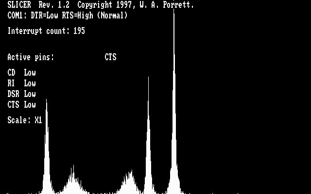
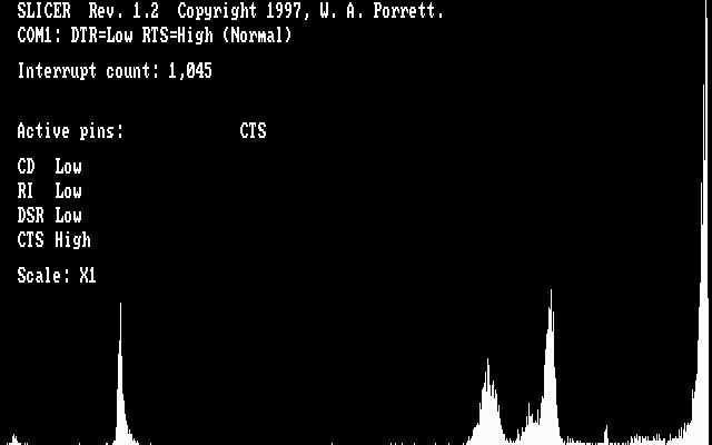
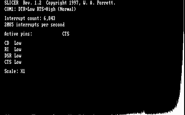
300 bps data is 300 bps data. SLICER doesn't care.but I do live within close proximity of several busy LTR Passport and Standard systems along with several Motorola systems (the busiest and strongest being a digital Motorola 3600 bps Smartzone system which I'm not sure the subaudable data would work the same way on or not, but could at least try).
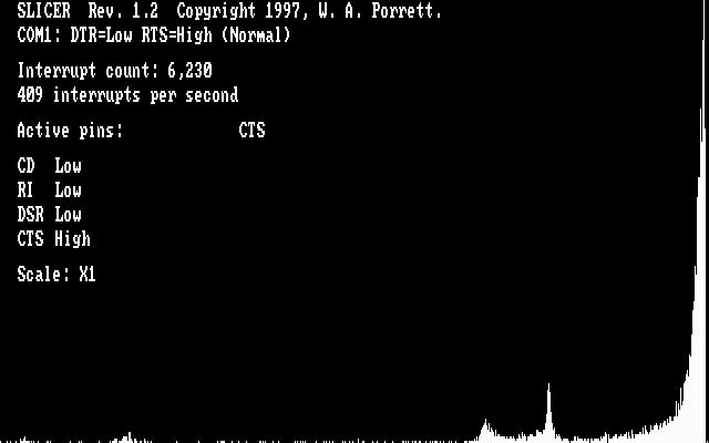
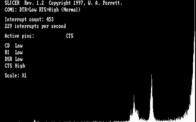
Those bursts are so short that they won't help you diagnose anything. You need voice comms.The Passports may also be excellent candidates because they have the idle burst every 3 to 5 seconds even when there is little to no voice traffic.
Cool. If you have them, clip leads are a good way to get accurate readings.I DO own a digital multimeter and will get to work and try both measuring the voltage while it's plugged in and verifying the correct resistance of all the resistors when its not.
CD, DSR and CTS are all suitable output pins. They are all treated the same by SLICER. Most decoding applications should also work with any of the three pins. My personal preference is CTS (pin 8)One final question for you - Since the diagram doesn't specify an RS-232 output pin, do you prefer one in particular? I've heard DSR and CTS will do the job, but do you know does any one have the best results with slicer.exe and LTRDump/LTRTrunk?
The negative side goes to the more negative point in the circuit. In the schematic's power section, where the two 1.0 uF caps are shown, your substituted electrolytics would have both of their (-) markings at the bottom, so your lower one is probably in backwards right now. It's a good thing serial ports can't pump out a lot of current; if they did, that cap would've blown up. No, I'm not kidding.
The only polarized capacitor I believe is the .033 uF one.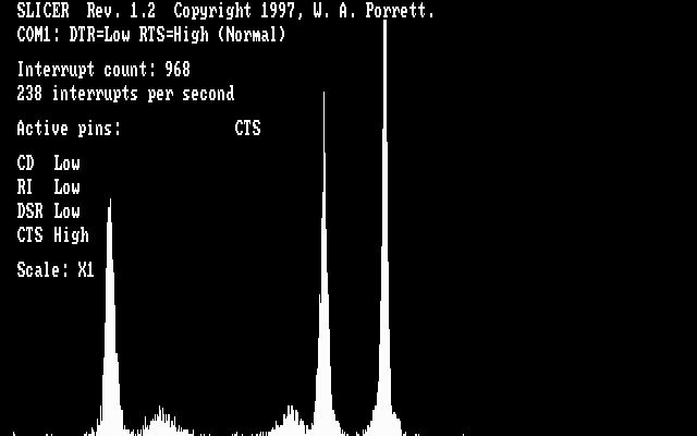
inigo88 said:Luckily all three 1.0uF capacitors are non-polarized and marked "NP" in the picture.