• To anyone looking to acquire commercial radio programming software:

    Please do not make requests for copies of radio programming software which is sold (or was sold) by the manufacturer for any monetary value. All requests will be deleted and a forum infraction issued. Making a request such as this is attempting to engage in software piracy and this forum cannot be involved or associated with this activity. The same goes for any private transaction via Private Message. Even if you attempt to engage in this activity in PM's we will still enforce the forum rules. Your PM's are not private and the administration has the right to read them if there's a hint to criminal activity.

    If you are having trouble legally obtaining software please state so. We do not want any hurt feelings when your vague post is mistaken for a free request. It is YOUR responsibility to properly word your request.

    To obtain Motorola software see the Sticky in the Motorola forum.

    The various other vendors often permit their dealers to sell the software online (i.e., Kenwood). Please use Google or some other search engine to find a dealer that sells the software. Typically each series or individual radio requires its own software package. Often the Kenwood software is less than $100 so don't be a cheapskate; just purchase it.

    For M/A Com/Harris/GE, etc: there are two software packages that program all current and past radios. One package is for conventional programming and the other for trunked programming. The trunked package is in upwards of $2,500. The conventional package is more reasonable though is still several hundred dollars. The benefit is you do not need multiple versions for each radio (unlike Motorola).

    This is a large and very visible forum. We cannot jeopardize the ability to provide the RadioReference services by allowing this activity to occur. Please respect this.

Making a Unity / M7300 Mobile 44-pin Speaker Cable - Help

brian86

Member
Database Admin
Joined
Mar 10, 2003
Messages
155
Location
Maryland
So I am by no means electronically inclined enough to understand exactly what I need to do to build my own speaker cable. I have 2 Front Mount Unity Radios with CH721 heads and would like to get away from the Harris Accessory Cable that is dawg gone near as bulky as the radio itself.

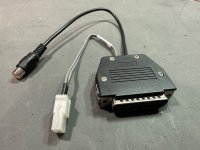
I purchased a 44pin breakout board to prototype and I have 44pin assemblies to make a finished product. First things first, I connected the speaker wire directly to pins 19/21 and I get nice clear audio.

I see in the schematic Below there are some loop-d-loops around Pin/Cable 19/20 & 21/22 that go to Pin7 Drain... 1680039565884.png

My question is what am I or how am I suppose to do that? Is that just shielding? I know Pin 7 is ground... I just don't want anything smoking in my shop.

Any help would be, well... very helpful. Thanks.
 

BMDaug

I am licensed…
Premium Subscriber
Joined
Jan 18, 2022
Messages
1,107
Location
Central Colorado, USA
Tie 19 and 20, then tie 21 and 22. 19/20 are positive, 21/22 are negative. 7 is tied to the shield of the Harris cable assembly.

Do NOT connect 7 to positive or negative. Just bridge 19/20, then bridge 21/22, (both at the 44pin connector) and connect those two leads to the speaker. Disregard 7 and the shield.

-B
 

brian86

Member
Database Admin
Joined
Mar 10, 2003
Messages
155
Location
Maryland
Thanks BMDaug, this is what I ended up doing... I made a pigtail that has the speaker Molex connector (19/20 & 21/22) and a RCA/Phono (14 & 1) out for connecting to a live stream (Radio Feed). So When I am out and about I can still monitor everything on the go. Seems to be working great.


I also changed the screw terminals on the rear DB44 female to Studs for this quick disconnect setup. You just have to squeeze the sides to release the connector. This makes it so much easier then trying to get a screw driver behind the radio in tight quarters.
 

Attachments

  • Speaker - AUX Output.jpg
    Speaker - AUX Output.jpg
    140.1 KB · Views: 20
  • Studs.jpg
    Studs.jpg
    154.9 KB · Views: 20

BMDaug

I am licensed…
Premium Subscriber
Joined
Jan 18, 2022
Messages
1,107
Location
Central Colorado, USA
That looks great! Just be careful swapping those Jack screws… they will shear off in the aluminum chassis if the threads are longer than the blind hole. Just FYI.

Also, if you are so inclined, the RCA could be wired to the FDISC output pin, which is a fixed level output so you can adjust the speaker volume independently of the stream feed. Just something for V2!!

Again, great job and much more compact than the official Harris solution!

-B
 

brian86

Member
Database Admin
Joined
Mar 10, 2003
Messages
155
Location
Maryland
That looks great! Just be careful swapping those Jack screws… they will shear off in the aluminum chassis if the threads are longer than the blind hole. Just FYI.

Also, if you are so inclined, the RCA could be wired to the FDISC output pin, which is a fixed level output so you can adjust the speaker volume independently of the stream feed. Just something for V2!!

Again, great job and much more compact than the official Harris solution!

-B
I seen the Forum about the FDISC output but I was lost when the notes in the manual said I needed to add components and stuff. Like I said I am not a very knowledgeable Electronics Component person. I was lost after the deformed u that came after the 33 below.

Use a 33 µF / 50 V (or greater) AC-coupling
capacitor to couple to a 600-ohm load
.
 

brian86

Member
Database Admin
Joined
Mar 10, 2003
Messages
155
Location
Maryland
Ah... It says 50V or greater. I just ordered

Nichicon FG Capacitors 63V 33uf Audio Grade​

off of Amazon as that was all I could find close that can be here by tomorrow. Hopefully it will work.

I am sure there is a correct way and an incorrect way to wire this in, I see one prong is longer then the other.
 

prcguy

Member
Joined
Jun 30, 2006
Messages
15,366
Location
So Cal - Richardson, TX - Tewksbury, MA
I seen the Forum about the FDISC output but I was lost when the notes in the manual said I needed to add components and stuff. Like I said I am not a very knowledgeable Electronics Component person. I was lost after the deformed u that came after the 33 below.

Use a 33 µF / 50 V (or greater) AC-coupling
capacitor to couple to a 600-ohm load
.
A capacitor will not change impedance. If the speaker output is designed for a 4-8 ohm speaker you want to give the radio a load resistor like 10 ohms then cap or resistor couple to a 600:600 ohm line transformer.
 

BMDaug

I am licensed…
Premium Subscriber
Joined
Jan 18, 2022
Messages
1,107
Location
Central Colorado, USA
Luckily, the equipment I needed to interface with already had the necessary components in place on its input stage, so I didn’t need to integrate any passives into my design.

But ya, that’ll work!

-B
 

BMDaug

I am licensed…
Premium Subscriber
Joined
Jan 18, 2022
Messages
1,107
Location
Central Colorado, USA
A capacitor will not change impedance. If the speaker output is designed for a 4-8 ohm speaker you want to give the radio a load resistor like 10 ohms then cap or resistor couple to a 600:600 ohm line transformer.
You wouldn’t attach a speaker to the FDISC output though. I think his plan is speaker output to speaker, FDISC to line level.

-B
 

brian86

Member
Database Admin
Joined
Mar 10, 2003
Messages
155
Location
Maryland
You wouldn’t attach a speaker to the FDISC output though. I think his plan is speaker output to speaker, FDISC to line level.

-B
Correct. That way the Line Level is a constant level and the speaker can be adjusted freely.
 

brian86

Member
Database Admin
Joined
Mar 10, 2003
Messages
155
Location
Maryland
Ahh, makes sense. Its still a good idea to transformer couple when connecting something like this to a computer audio input.
Recommendation on the Part I should use to accomplish this? and maybe a quick wiring explanation. If its explained in layman terms I can probably get the components and solder everything. I do thank you all for your input.
 

prcguy

Member
Joined
Jun 30, 2006
Messages
15,366
Location
So Cal - Richardson, TX - Tewksbury, MA
This should work for the constant line level to a computer. Cut the center pin off of each side then solder the pins on one side to the radio cable then the pins on the other side to the cable feeding the computer. Polarity doesn't matter much in this case.
 

brian86

Member
Database Admin
Joined
Mar 10, 2003
Messages
155
Location
Maryland
This should work for the constant line level to a computer. Cut the center pin off of each side then solder the pins on one side to the radio cable then the pins on the other side to the cable feeding the computer. Polarity doesn't matter much in this case.
I had already ordered these... Will they work?

https://www.amazon.com/gp/product/B07Q6RSWYC/ref=ppx_yo_dt_b_asin_title_o00_s00?ie=UTF8&th=1
 

mancow

Member
Database Admin
Joined
Feb 19, 2003
Messages
6,880
Location
N.E. Kansas
What is FDISC? I assumed it would be short for Flat DISCriminator with potentially no squelch no subaudible filtering and no deemphasis.
 

BMDaug

I am licensed…
Premium Subscriber
Joined
Jan 18, 2022
Messages
1,107
Location
Central Colorado, USA
What is FDISC? I assumed it would be short for Flat DISCriminator with potentially no squelch no subaudible filtering and no deemphasis.
“Buffered Filtered Discriminator Audio Output (typically not used). A fixed-level audio output with DC bias. Approximately 200 mV rms into a 600-ohm load at rated deviation. Does not contain signaling (e.g., CTCSS). Mutes when speaker mutes. Use a 33μF/50V (or greater) AC-coupling capacitor to couple to a 600-ohm load. Use P4 pin 12 for ground.”

From the manual.

-B
 
Top