MilAir Antenna from ST-2 Design

Status
Not open for further replies.

digitalanalog

Active Member
Joined
May 18, 2007
Messages
562
Location
United States of America
From my other massive amounts of testing on the ST-2 antenna and the ST-2 type designed
(the Searcher II)I have been working on, I determined that it would take RADICAL changes
the ST-2 prototype antenna I have been working on to get it into the 200-400MHz range
without jepordizing other bands on the antenna.

So I decided to build a 200-400MHz ST-2 style antenna and build it to ONLY work in that
range 200-400MHz, if it happens to work in other ranges then it's just a bonus, but I did
not care or consider other freq bands, just the MilAir 200-400MHz. (yes i know milair is in other bands)

No front radials of any kind, no connecting rods tieing the sections together, and no wings were required.
(I had a left over main tube from the other antenna design, thats why the extra insulators are there but Not
used, I just didn't take them off.)

75-300 Ohm transformer was used, 75 Ohm RG6 coax was used, Tested using MINI VNA, Calibrated to 75 OHm.

Each element was cut to a specific 1/2 wave length in the spread of 200-400MHz range.
all elements are of different lengths and cut as mentioned to 1/2 wave length dimensions
instead of the typical 1/4 wave length.

I am VERY happy with the results, I have made NO Adjustments to the elements, they are as the
On-Line Wave length Calculator indicated they should be for the range I desired.

The lower end is not as low as I would like and I may try to adjust that, but I have not decided
at this point that it would even be worth it without at least doing to realtime listening on the scanners.

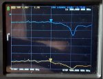
01.jpg

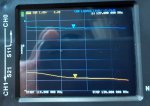
02.jpg

03.jpg

vna200400.jpg
 

vagrant

ker-muhj-uhn
Premium Subscriber
Joined
Nov 19, 2005
Messages
3,177
Location
California
How long was the cable for this test? Have you measured the results using different lengths of RG6, say 25', 50', 75' and or 100'?

What does the sweep look like if you start at 118 or 138 MHz?
 

iMONITOR

Silent Key
Premium Subscriber
Joined
Sep 20, 2006
Messages
11,156
Location
S.E. Michigan
Your antenna designs have my attention. When might they be available for sale? What are the dimensions of this one?
 

cmdrwill

Member
Joined
Mar 30, 2005
Messages
3,984
Location
So Cali
Your antenna designs have my attention. When might they be available for sale?

I am thinking, I know I should not, but what about a two meter Ham antenna? Would be great for HOA and stealth applications.
And maybe other ranges?
 

digitalanalog

Active Member
Joined
May 18, 2007
Messages
562
Location
United States of America
A few corrections/edits I noticed from the OP.

Quote: "75-300 Ohm transformer was used, 75 Ohm RG6 coax was used, Tested using MINI VNA, Calibrated to 75 OHm."
EDIT: I used a NANO VNA for testing. NOT a MINI VNA

Quote: "The lower end is not as low as I would like and I may try to adjust that,"
EDIT: The HIGHER end is not as low as I would like it. The Lower end is pretty good actually.

per Vagrant previous comments.
I did a 118-138MHz sweep and a 118-400MHz sweep as well, will try to get those images uploaded later today.

I decided to check this antenna for all around freq. even if It was designed to only work in the 200-400MHz range and it only looked good in one other area, by the length of the radials what would you guess?

more later today (i hope).
 

vagrant

ker-muhj-uhn
Premium Subscriber
Joined
Nov 19, 2005
Messages
3,177
Location
California
You can just tell us the result of those air band sweeps, like if it was under 2:1.

As for the range guess, 60-140. I am guessing your 200-400 result is third harmonic.
 
Last edited:

digitalanalog

Active Member
Joined
May 18, 2007
Messages
562
Location
United States of America
Here is the sweep from 118-138MHz (civil air band)

118138cropped.jpg

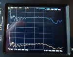
This is 118-400MHz (Civil Air-Milair)

118400cropped.jpg

And inreference to what other band this antenna look very good in.
not the 60-140MHz that Vagrant guessed.
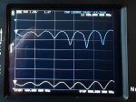
But this is a scan from 400-500MHz. and it looks very good for the 400MHz public service band.

400500cropped.jpg

All in all, I think this worked out well, I still might try to get the 225-300MHz section lower if I can.
I will see how it receives in the 118-138MHz band when I get it up on the mast pipe, but it
doesn't look all that hot according to the sweep, but who knows.
 

Ubbe

Member
Joined
Sep 8, 2006
Messages
9,033
Location
Stockholm, Sweden
If you are using that 300/75 ohm transformer I would think that its 4:1 ratio would make the antennas imperfections read as 4 times less at the 75 ohm side?

My Diamond X510 had god and low SWR and S11 vaules in the amateur bands but nowhere else and reception was not fantastic outside of its amateur bands. Then I removed most of its impedance compensating circuits and got a terrible 3:1 SWR at best but all bands have a healthy boost is signal strenght and the amateur bands are still as good, if not better, than it originally had. It's probably useless to transmit into but works wonderfull as a reception antenna, even at 5:1 and worse SWR. So I guess that practical A-B reception tests are best way to evaluate antennas.

/Ubbe
 

digitalanalog

Active Member
Joined
May 18, 2007
Messages
562
Location
United States of America
If you are using that 300/75 ohm transformer I would think that its 4:1 ratio would make the antennas imperfections read as 4 times less at the 75 ohm side?

/Ubbe
If the antennas imperfections read 4 time less then it would mean 4 times worse.

So then, is it your assumption that this antenna is 4 times worse then the analyzer shows?
which would mean the ST-2 analyzer readings would also make it 4 times worse and my Searcher antenna as well?
and all because of the transformer?

or Did I miss your point?

Not trying to be cocky, just not sure what that statement is suppose to mean.
 

Ubbe

Member
Joined
Sep 8, 2006
Messages
9,033
Location
Stockholm, Sweden
Let's say that the antennas impedance has variations from 50 to 1000 ohms over a frequency range. The 4:1 transformer would make that look like 12 to 250 ohms at the end you connect to the 50 ohm analyzer. You would see a worst SWR of 250/50 = 5:1
If you connect the analyser directly to the antenna you would see 1000/50 = 20:1
That's the main reason for the use of the transformer, to make the antenna match better to the coax when it is used outside of it's tuned frequency.
The disadvantage are, as is always with antennas that you cannot have the cake and eat it too, that it will transform the received signal voltage from the antenna to a lower value. You make the antenna more broadbanded but also sacrifice signal strenght at the frequencies where the antenna are perfectly matched to the coax.

When using a scanner you probably want the antenna to work over a big frequency range, like a discone, but the dipol type of antenna does not have the disadvantages as discones have at the 800MHz band and the ST-2 type have a dipole for the 40MHz band when a discone are made for 90Mhz and upwards. So the ST-2 type will work better at both low-vhf and 800Mhz bands and the transformer will smooth out the SWR in the gaps between the different dipole elements tuned frequencies.

/Ubbe
 

digitalanalog

Active Member
Joined
May 18, 2007
Messages
562
Location
United States of America
This antenna was only made to work at 200-400MHz. Nothing More Nothing Less
As i posted originaly, if it works in other areas then its just a bonus, such as the good
results it has in the 400-500MHz.

it's not a wide band antenna

its like other specifically tuned antennas designed/built to work in 1 section of a certain band.

how it performs in that area is my ONLY concern.

I wont know how well it actually receives in the area I made it for until I put it up in the air and listen to it.
the analizer shows it is well within the specs for the band it was designed for, if we can't rely on analzyers to be a building block for antenna designs then what the hell good are they.
 

Ubbe

Member
Joined
Sep 8, 2006
Messages
9,033
Location
Stockholm, Sweden
It would probably be difficult to find a constant level transmission in the 200-400MHz range, but if you do then listen and try and see the signal strenght with something like a SDS scanner and then make a short coax cable that you could connect to the coax instead of the transformer and splice the coax end and connect to the antenna and compare the signal strenght.

The best test would had been if you had a 75/75 transformer or if you could put a choke balun on the coax, several ferrite rings, to decouple the coax from the antenna. Then test with your analyzer and compare to your listening results. It would had been interesting to see the difference.

/Ubbe
 

w4rtt

Member
Joined
May 7, 2010
Messages
174
Location
Independence, KY
1602735446728.png

Where the long element connects to the insulator, the shaft appears to be square. How is this accomplished.

Randy
W4RTT
 
Status
Not open for further replies.
Top