Multipath in Doppler vs. Multi-coherent receivers (Kerberos/Kraken SDR)

Status
Not open for further replies.

aaknitt

Member
Feed Provider
Joined
Aug 27, 2005
Messages
1,300
Disclaimer: I'm just getting into RDF so a lot of this is new to me.

If I understand correctly, "good" doppler RDF designs use multiple PIN diodes to not only switch which antenna in the array is connected to the receiver at any given time, but to also switch the other "unused" elements to a high impedance state at center of the antenna in order to minimize their impact as parasitic elements that would create a directional radiation pattern. By switching them to high impedance, they are essentially two separate 1/4 wave elements that become relatively "invisible" to the antenna that's in use.

If that's the case, I'm thinking that it may be difficult or impossible to eliminate the parasitic effects in something like a Kerberos (now Kraken) SDR in which all four elements are continuously connected to four different (50-ish ohm) SDR receivers (no PIN diode switching)? And that therefore these coherent SDR RDF setups may be inherently more susceptible to multipath than a doppler set that uses switched antenna elements?

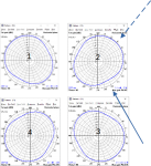
I did some rudimentary modeling in EZNEC (I'm a complete novice at this so I may have badly messed it up) that seems to show that when a single antenna is fed and the others have a high impedance at the center, the pattern of the fed antenna is very omindirectional, as we would want:
1641354829967.png

When the same antenna is fed but the other three antennas have a 50 ohm impedance at their centers, the pattern becomes distorted:
1641354885981.png

It looks like there is about 6 dB of directionality when all four antennas are connected to 50 ohm receivers at the same time. So if a multipath signal comes in at the right angle, it could be "overpowering" the "true" signal if it's within 6 dB. I'm not sure how likely that is.

Is my understanding correct, and if so, is there any workaround to address this when using the coherent SDR RDF rigs?
 

slicerwizard

Member
Joined
Sep 19, 2002
Messages
7,643
Location
Toronto, Ontario
For starters, all of the antennas are not going to have gain in the direction of the multipath signal. All inputs are always active and always being used to calculate signal directions.
 

aaknitt

Member
Feed Provider
Joined
Aug 27, 2005
Messages
1,300
Right, but consider the scenario that I've tried to crudely illustrate below. The direct signal is the solid line coming in at about 300 degrees. The multipath signal is 3 dB lower, coming in at 45 degrees. Antenna/receiver #2 will then see the multipath signal as stronger than the direct due to the pattern distortions. Assuming the system then uses the multipath signal for processing, it will introduce two errors:
  • Where normally the signal (plane wave coming from 300 degrees) arrives at antenna/receiver #2 arrives before it arrives at #1, the receiver will instead see #2 arriving after #1 due to the multipath
  • The time between the signal (plane wave) arriving at #2 relative to #3 will be longer due to multipath
I think that these errors would be enough to really throw off the DOA estimation. Granted this is a very specific scenario and this certainly isn't a show-stopper for this method, I'm just wondering out loud if perhaps the "older fashioned" doppler RDF has some inherent advantages with regards to multipath performance. I may be totally wrong.

Andy
1641871305414.png
 

PA8W

Newbie
Joined
Nov 14, 2017
Messages
17
I think your assumptions are right Andy.
If you change the simulation frequency to some extend above and below the designing frequency you will notice that the directional pattern of the antennas change a lot, depending on the parasitic antennas acting as a reflector or as a director.
That also has an impact on the received phase.
In my opinion that increases the impact of multipath.
I can't really estimate the magnitude of error that is produced by this phenomenon.
Therefore I greatly miss a thorough field test that exactly shows the errors over the entire 360 degrees circle and at a number of frequencies around (below and above) the designing frequency.
Until that field test is published we won't know how serious the problem is.
In professional correlative interferometers the measured phase of all antennas is compared to an array of theoretical data.
This way errors of an array might be corrected.
But again, until a solid field test is performed with the Kraken and Kerbeross we can only guess if and to what degree performance is degraded.

Wil
Pa8w
 

aaknitt

Member
Feed Provider
Joined
Aug 27, 2005
Messages
1,300
I think your assumptions are right Andy.
If you change the simulation frequency to some extend above and below the designing frequency you will notice that the directional pattern of the antennas change a lot, depending on the parasitic antennas acting as a reflector or as a director.
That also has an impact on the received phase.
In my opinion that increases the impact of multipath.
I can't really estimate the magnitude of error that is produced by this phenomenon.
Therefore I greatly miss a thorough field test that exactly shows the errors over the entire 360 degrees circle and at a number of frequencies around (below and above) the designing frequency.
Until that field test is published we won't know how serious the problem is.
In professional correlative interferometers the measured phase of all antennas is compared to an array of theoretical data.
This way errors of an array might be corrected.
But again, until a solid field test is performed with the Kraken and Kerbeross we can only guess if and to what degree performance is degraded.

Wil
Pa8w

Wil,

Your site has been a phenomenal source of information, thanks for making it all available! I'm hoping to start building a doppler setup in the spring once its a bit warmer outside for easier testing.

Since I don't really have any real experience with either doppler or Kerberos, I'm not sure what's "normal" when it comes to multipath performance. I'd be interested in your thoughts on this video starting at about the 7:30 mark where he does a walkaround of the vehicle with a transmitter. There seem to be quite a few occasions where the compass isn't pointing in the correct direction. Would that be happening on a doppler in a similar test, or does it seem that maybe the Kerberos has some worse issues with multipath?

I have a Kerberos and did a very brief test in my backyard about a month ago and I wasn't very impressed with the results, but I'm not sure what "normal" performance is with a doppler. It got too cold for me to continue testing, but in the spring I'll do some more.

It seems that a large part of the Kerberos method is averaging bearings while driving to smooth out the multipath effects. I'm sure that works well, but it can also work just as well or better with a doppler, I would assume. I'm most interested in DFing from a stationary location, so if Kerberos uses averaging while driving as a "crutch" against multipath I'm afraid it may not be a good solution for my application.

Andy
 

PA8W

Newbie
Joined
Nov 14, 2017
Messages
17
Averaging is indeed a key ingredient for producing a stable reading.
In my RDF's I start averaging by collecting more than 100 antenna rotation samples in a switched capacitor filter.
Around 4 times per second, these capacitors are then sampled to generate a digital value, ready for processing.
These values are given a Quality judgement, to kick out the values that obviously have been distorted by multipath reception.
The remaining values are used to calculate a long term average, resulting in a very stable and pretty reliable bearing.

Watching the video you suggested I noticed the severe errors that occur walking around the car. I presume this was on a UHF freqency.
These errors are much, much more severe than I notice doing the same kind of test on UHF. (Higher frequencys are more prone to reflections)
I can think of 2 reasons for that:
1, The Kerberos system doesn't recognise distorted (multipath) measurements.
2, The array isn't optimal, resulting in cable-pickup that acts the same as multipath reception.

It might be both...

In stationary use we miss a lot of the advantage of averaging, but not all, let me give you two examples:

1, In my home setup I can see waving trees (high wind) in my vicinity "pull" at the received bearing.
The thousands of micro-reflections of these big trees all ad-up differently when the trees are waving in the wind.
That ever changing, noise-like condition is cancelled to a large degree by averaging.
Also my quality algorithm gives some additional improvement here.

2, In a certain direction I see increased bearing errors of which I think are caused by a massive metal power plant at a few kilometers distance.
This giant building acts as a mirror for radio signals.
In situations where I receive a good direct signal this power plant reflection is added to the direct signal, resulting in some accuracy error.
I do recognise however that I receive multipath, thanks to the Quality judgement.
Hoever, is the radio source is just beyond the horizon, the power plant reflection is the "truth" for my RDF, since there's no way it can know that the only received signal is a reflection.

All together, both techniques -averaging and the quality algorithm- work excellent for mobile use but they are clearly less effective in static setups.
Having said that, my experience is that even my home-setup shows an average accuracy error of less than 5 degrees on UHF signals.
Signals from radiosondes that land in my vicinity (<20km) show an average error of 1 to 2 degrees, just before landing.
(To be complete I have to mention that my stationary UHF setup is not a pseudo doppler but an amplitude system using a GP antenna with 4 switchable reflectors, but performance is very close to a pseudo doppler setup)

Sorry I needed so much text to clarify this... :)

Wil
Pa8w
 

aaknitt

Member
Feed Provider
Joined
Aug 27, 2005
Messages
1,300
Wil,

Thanks for the feedback, this is very helpful! What I'm interested in DFing is VHF airband transmissions, which tend to be very short. I kind of like the idea of an amplitude DF system since VHF airband uses AM anyway, so finding a receiver may be easier. On the other hand, I'd also like to try your method of elevation estimation since that would be really useful for what I'm trying to do. I think that would only work with doppler though? Do you have any suggestions for DFing short, bursty VHF AM transmissions from aircraft from a stationary location?

Andy
 

PA8W

Newbie
Joined
Nov 14, 2017
Messages
17
Andy,
The elevation indicator is only reliable at clean (non-multipath) signals of at least a few seconds of duration.
Therefore it is of limited value. During a hunt for a radiosonde however it does give me a fair spatial indication.
So, ignoring the elevation indicator, an Amplitude system would be a good alternative, giving you good "listen through" capability and ease of finding a proper receiver.
PA8W Amateur Radio Direction Finding, good challenge, great fun! shows you the Amplitude antenna array which I use on UHF for the last few years now.
It can be scaled up in size for say 130MHz design frequency and cover the entire VHF air band with a predictable and uniform directional pattern.
In "antenna test mode" I can step through all 4 directions with a bit of additional gain to listen to (or decode) weak signals.
So it doubles as a simple rotatable reception antenna.
If you want I can calculate sizes for you for the VHF airband. Just let me know.
But Eznec can do the same for you. It's extremely educating to do your own antenna modeling. ;)

Cheers,
Wil
Pa8w
 
Status
Not open for further replies.
Top