• To anyone looking to acquire commercial radio programming software:

    Please do not make requests for copies of radio programming software which is sold (or was sold) by the manufacturer for any monetary value. All requests will be deleted and a forum infraction issued. Making a request such as this is attempting to engage in software piracy and this forum cannot be involved or associated with this activity. The same goes for any private transaction via Private Message. Even if you attempt to engage in this activity in PM's we will still enforce the forum rules. Your PM's are not private and the administration has the right to read them if there's a hint to criminal activity.

    If you are having trouble legally obtaining software please state so. We do not want any hurt feelings when your vague post is mistaken for a free request. It is YOUR responsibility to properly word your request.

    To obtain Motorola software see the Sticky in the Motorola forum.

    The various other vendors often permit their dealers to sell the software online (i.e., Kenwood). Please use Google or some other search engine to find a dealer that sells the software. Typically each series or individual radio requires its own software package. Often the Kenwood software is less than $100 so don't be a cheapskate; just purchase it.

    For M/A Com/Harris/GE, etc: there are two software packages that program all current and past radios. One package is for conventional programming and the other for trunked programming. The trunked package is in upwards of $2,500. The conventional package is more reasonable though is still several hundred dollars. The benefit is you do not need multiple versions for each radio (unlike Motorola).

    This is a large and very visible forum. We cannot jeopardize the ability to provide the RadioReference services by allowing this activity to occur. Please respect this.

My RM Italy blew up!

Status
Not open for further replies.

prcguy

Member
Joined
Jun 30, 2006
Messages
15,366
Location
So Cal - Richardson, TX - Tewksbury, MA
Looks like you lost one of the PA transistors, which I believe are FETs in that model. If the amp was not in use and in transmit mode then a PA transistor should not be affected from a nearby lightning strike, only things in the through path back to the radio might receive a jolt.

So here’s the insides. The humorous part is the tiny little fuse in the second picture is still good to go. So whatever those parts are on the top and bottom just has a catastrophic failure that didn’t seem to affect the rest of the amp.
 

ClemsonSCJ

Member
Joined
May 29, 2018
Messages
227
Yeah, looks like RF amps.
Fuse didn't open because it wasn't a fault that would do that.
Looks like you found the limits on how close you can be to a lightning strike with this setup.
I'd count yourself lucky that there wasn't damage to the truck or anyone in it.
So the questions stands...would a lightning arrester grounded to the truck chassis have helped mitigate this affect? I know nothing about these components so does that seem like a plausible thing to have blown with lightning surges?
 

prcguy

Member
Joined
Jun 30, 2006
Messages
15,366
Location
So Cal - Richardson, TX - Tewksbury, MA
Probably not. If in the million to one chance your truck created the streamer for the lightning path off your CB antenna then a "lightning rod" on the truck that sticks up much higher than the antenna should carry most of the strike. But both the antenna and lightning rod would be within the confines of the truck which is not very big considering the lightning may have traveled 5 miles to you and the two things sticking up on a truck maybe 10ft apart probably doesn't mean that much to Mr. Lightning.

So the questions stands...would a lightning arrester grounded to the truck chassis have helped mitigate this affect? I know nothing about these components so does that seem like a plausible thing to have blown with lightning surges?
 

RFI-EMI-GUY

Member
Joined
Dec 22, 2013
Messages
6,877
Does the diode go from the “85 to 86” terminal of the relay or the “30 to 87”?

DIN terminals 85 and 86, the coil winding. The diode should be reverse biased (Bar toward +) when voltage is applied deliberately across the coil . A 1N4004 or better a 1N4007 diode should be used.
 

RFI-EMI-GUY

Member
Joined
Dec 22, 2013
Messages
6,877
So the questions stands...would a lightning arrester grounded to the truck chassis have helped mitigate this affect? I know nothing about these components so does that seem like a plausible thing to have blown with lightning surges?

You could put a lightning arrestor on the equipment.

Assuming the lightning did not directly hit the antenna, I suspect the RM Italy itself was getting its ground solely from the coax and the black power lead and circulating currents spiked the PA transistor. Next go around, make sure that it is bonded to the sheet metal body of the vehicle. Hoping your President radio survived. Wow!
 

slowmover

Active Member
Joined
Aug 4, 2020
Messages
1,903
Location
Fort Worth
You could put a lightning arrestor on the equipment.

Assuming the lightning did not directly hit the antenna, I suspect the RM Italy itself was getting its ground solely from the coax and the black power lead and circulating currents spiked the PA transistor. Next go around, make sure that it is bonded to the sheet metal body of the vehicle. Hoping your President radio survived. Wow!

Having wondered the same a few years ago I drilled part of the heat sink at an outer corner to accept a sheet metal screw to help “clamp” the device down.

Better method would be?

.
 

RFI-EMI-GUY

Member
Joined
Dec 22, 2013
Messages
6,877
Having wondered the same a few years ago I drilled part of the heat sink at an outer corner to accept a sheet metal screw to help “clamp” the device down.

Better method would be?

.

Post 19 shows the negative lead connected at the middle of the PCB. Since the PCB slides loosly in to the heatsink case there does not seem to be any bonding of the edge of the PCB. Current returning on the case might go through the MOSFET leads to the heat sink tabs, if at all. I would bond the extruded case and the negative lead together and bond both at vehicle chassis sheetmetal. If it were not for the OP mentioning an nearby lightning strike I would have blamed infant mortality or the control relay spiking the MOSFET. I am blaming a surge on the wiring, but it is so rare for vehicles to have electronic damage unless they are struck directly.
 

FiveFilter

Member
Joined
Jan 1, 2016
Messages
308
Since my mobile radio equipment is installed as a "slip-seater" tool, ie non-permanent and easily moved from vehicle-to-vehicle, I use a wire and alligator clips to ground my radios and the 203P to the vehicle chassis. This is done to bleed any common mode current off. But, possibly it could help with lightning strikes, although to do any good the strike would have to be a mighty weak one to be handled by the 10-gauge wires involved. And after passing through the antenna/amp/radio/chassis, where does it go? It would have to jump to earth, but there's no wiring for that path, so it takes a leap to ground. My head hurts.
 

slowmover

Active Member
Joined
Aug 4, 2020
Messages
1,903
Location
Fort Worth
Post 19 shows the negative lead connected at the middle of the PCB. Since the PCB slides loosly in to the heatsink case there does not seem to be any bonding of the edge of the PCB. Current returning on the case might go through the MOSFET leads to the heat sink tabs, if at all. I would bond the extruded case and the negative lead together and bond both at vehicle chassis sheetmetal. If it were not for the OP mentioning an nearby lightning strike I would have blamed infant mortality or the control relay spiking the MOSFET. I am blaming a surge on the wiring, but it is so rare for vehicles to have electronic damage unless they are struck directly.


Makes sense. And it’s easy to do.

1). I upgraded wiring on the first RM 203-series amp as I was uncomfortable with the size supplied.

2). Drilled the corner “hole” (thru fins) at same time.

3). (Now to complete the procedure!)

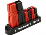
— In the big truck I use a POWERWERX PD-75 to supply radio & etc from 6-AWG in a 19’ run (on a BLUE SEA 30A Termination Fuse at BATT).

— The amp pair is about one foot from 12V distribution. The Mains NEG is another foot or so. (These last two are location-dependent, unlikely to be shorter.)

2DD15695-DCB3-439F-8F38-D788C42DDEFF.jpeg

Bonding the upgraded Amp Neg Wire + new Amp Case Ground Screw (or Nut/Bolt) seems a good idea.

Thx

.
 
Last edited:

slowmover

Active Member
Joined
Aug 4, 2020
Messages
1,903
Location
Fort Worth
Since my mobile radio equipment is installed as a "slip-seater" tool, ie non-permanent and easily moved from vehicle-to-vehicle, I use a wire and alligator clips to ground my radios and the 203P to the vehicle chassis. This is done to bleed any common mode current off. But, possibly it could help with lightning strikes, although to do any good the strike would have to be a mighty weak one to be handled by the 10-gauge wires involved. And after passing through the antenna/amp/radio/chassis, where does it go? It would have to jump to earth, but there's no wiring for that path, so it takes a leap to ground. My head hurts.


The Radio Case, like the Amp case, not connected internally?

Unlike some of my other experiments, “case ground” hasn’t yielded results for me.

Maybe now I know why. Easy enough to try (assuming I don’t set a ground loop).

I usually sprinkle a few handfuls of ferrites over the radio rig after it comes out of the oven (been installed), but running wire or braid to case screws has not yielded audible differences.

(Where the radios are NOT screwed to a rack; itself screwed to metal; just a Velcro strap as provided in a big truck).

.
 

slowmover

Active Member
Joined
Aug 4, 2020
Messages
1,903
Location
Fort Worth
Side Note: The POWERWERX PD-75 features an internal heavy buss bar unlike some lower-priced alternatives using circuit traces.

For someone without APP (Anderson Power Pole) Tools & Supply it’s a chunk of change to move up. My experience is that I wish I’d done it years ago.

For purposes of this thread device removal and inspection is a snap.

My attitude about MOBILE is that Devices are of themselves unimportant compared to ANTENNA and POWER systems. They’re just components that might get swapped out at a moments notice. They plug into the Radio System.

The PD-75 is a fixed part of POWER. Radio, amp, etc, are not.

APP made this much easier for me to accomplish. Removing and modifying the AMP NEG wire leaves the focus on the modification (the energy expenditure) versus splices or screw-down 12V distribution; thus 3X the effort in a cramped space.

I find out I goofed (radio chassis ground), it’s just as easy to fix.

I smoke a 203, the spare just plugs in.

Modularity

.
 

RFI-EMI-GUY

Member
Joined
Dec 22, 2013
Messages
6,877
So is the diode meant to protect the relay or the device being powered?

It is good practice to have a back EMF diode on relays, solenoids and even motors so that any electronics sharing the 12V supply circuit don't see any negative voltage spikes. The relay does not care.
 

prcguy

Member
Joined
Jun 30, 2006
Messages
15,366
Location
So Cal - Richardson, TX - Tewksbury, MA
Most mobile amps have a big reverse protection diode across the 12V buss that will clamp anything above about .6 volts going the wrong direction. No real need for individual diodes across each relay in that case.

It is good practice to have a back EMF diode on relays, solenoids and even motors so that any electronics sharing the 12V supply circuit don't see any negative voltage spikes. The relay does not care.
 
Status
Not open for further replies.
Top