So I want to work some satellites with my handheld radio, and I couldn't hear any of the packets from the ISS using a Nagoya whip on the radio, a 1/4 wave ground plane, a magnet mount mobile antenna, or a TV twin lead slim jim. granted, the passes were not optimal. But I have been wanting to try this antenna for a while so I finally got the parts yesterday and built one.
Here is the link I used for the instructions:
http://theleggios.net/wb2hol/projects/rdf/tape_bm.htm
All of the element lengths and spacing are taken right from these plans, along with the length of the wire used for the hairpin match.
The plans call for attaching all of the elements using stainless hose clamps, but the author does mention that he would use screws to attach the director and reflector to reduce weight and bulk. He also states that the screws would weaken the tape. Additionally, he mentions some builders using rubber washers as spacers to help the tape match the radius of the pipe fittings.
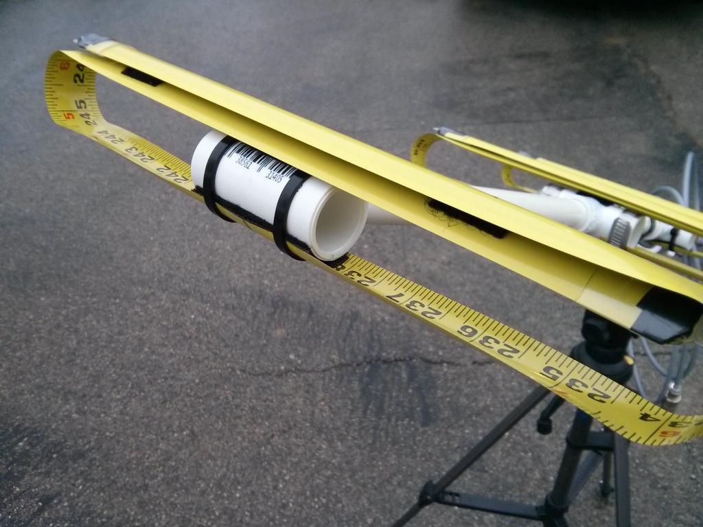
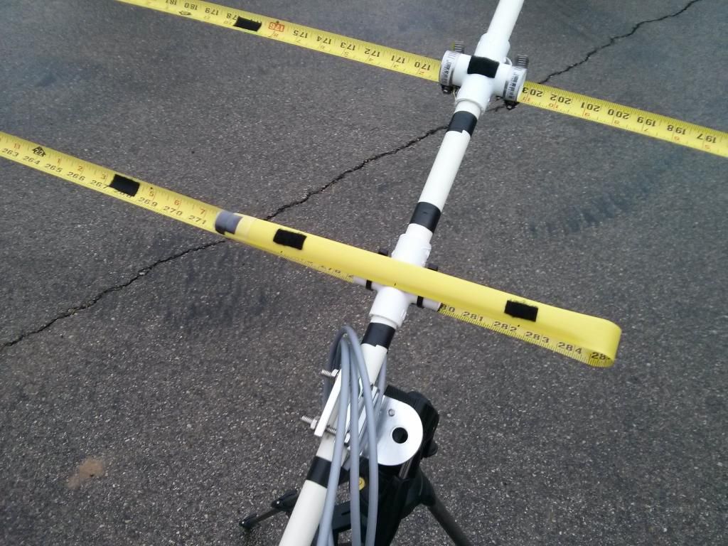
I decided to use some industrial strength Velcro to mount the director and reflector elements, and reinforce the joints with nylon zip ties. This seems to work well, and doesn't weaken the tape by putting holes in it. It also has the added benefit of making a better match to the radius of the pipe, similar to the washers described in the original article.
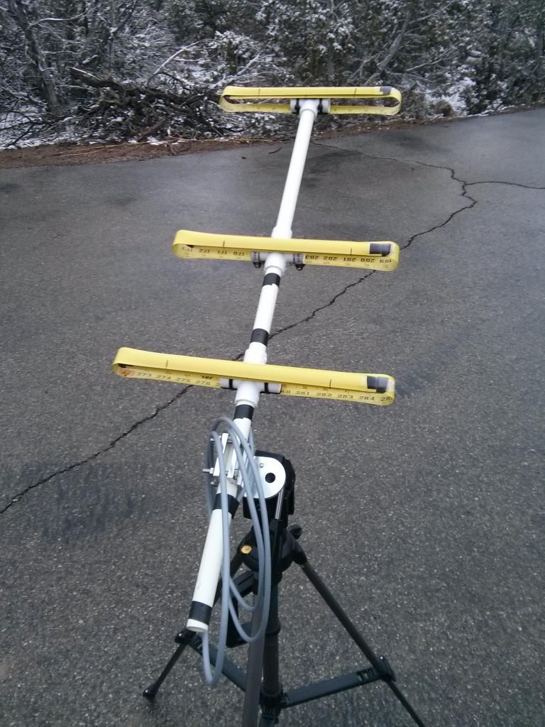
I then went one step further and added velcro bits to hold the elements in a folded configuration for easier storage and transport. I have seen some guys roll them up individually but that seems to be too fiddly and time consuming. folding the elements and detaching the director makes the whole thing collapse down to a very reasonable size.
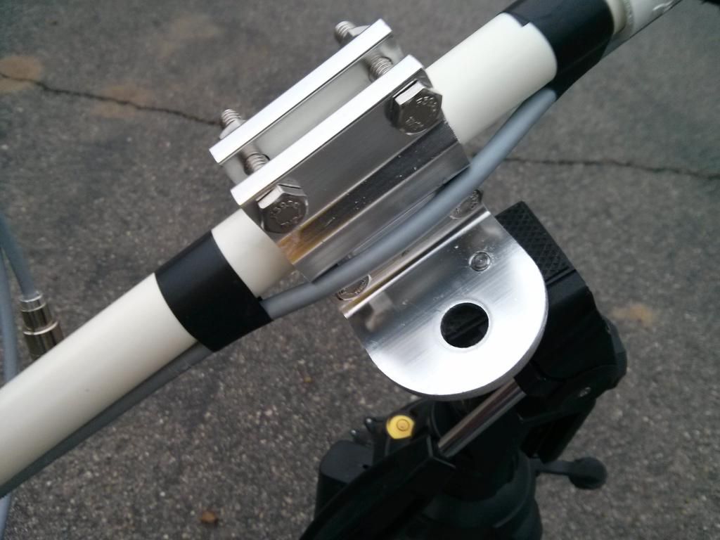
To mount it I used a CB antenna mirror mount that I drilled and tapped with 1/4-20 threads to mate with a standard camera tripod. It is light enough not to tip over, and this tripod has a hook for hanging a sandbag to add weight if needed. If the antenna needs to be stiffened up for windy conditions, you could just stick some PVC into the sides of the fittings and tape the elements down (or use more velcro).
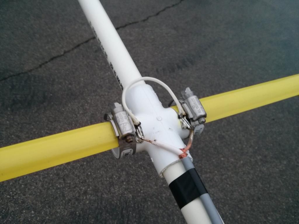
The hardest part of the whole operation was holding solder, soldering iron, hairpin match, and cable all at once. My 'helping hands" were not enough. Just as was advised in the article, I tinned everything first. However, the article advises against soldering everything in place because it could melt the PVC fittings. I found that slipping a scrap piece of tape measure under the piece being soldered, and loosely clamping them both onto the fitting allowed me to solder the connections in place without melting the pipe, though the insulation on the hairpin took a beating.
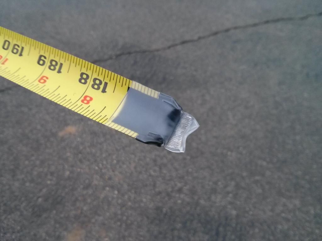
I will probably eventually get a 1"-3/4" reducer and an end cap and mount an SO239 in the end and route the cable through the inside of the mast. I also want to get some plasti-dip for the ends of the elements. For now I used electrical tape covered with heat shrink but the dip would be a more streamlined solution. I looked 4 places and nobody stocked it.
The match is not perfect but it is good enough to satisfy me. It is under 2:1 SWR from 144.000 to 148.000 MHz, and under 1.2:1 at 145.825 as verified with an MFJ-259C.
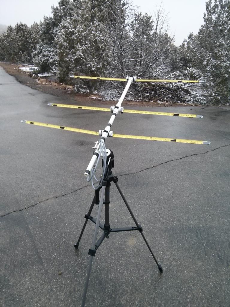
Here are a few pics. It is my first scratch built Yagi so go easy on me!
Fully deployed:
Elements folded:
Detail of director mounting with Velcro and zip ties:
Connections and hairpin match:
Velcro tabs to fold elements:
Detail of mount:
End protection:
Thanks for looking!
Here is the link I used for the instructions:
http://theleggios.net/wb2hol/projects/rdf/tape_bm.htm
All of the element lengths and spacing are taken right from these plans, along with the length of the wire used for the hairpin match.
The plans call for attaching all of the elements using stainless hose clamps, but the author does mention that he would use screws to attach the director and reflector to reduce weight and bulk. He also states that the screws would weaken the tape. Additionally, he mentions some builders using rubber washers as spacers to help the tape match the radius of the pipe fittings.
I decided to use some industrial strength Velcro to mount the director and reflector elements, and reinforce the joints with nylon zip ties. This seems to work well, and doesn't weaken the tape by putting holes in it. It also has the added benefit of making a better match to the radius of the pipe, similar to the washers described in the original article.
I then went one step further and added velcro bits to hold the elements in a folded configuration for easier storage and transport. I have seen some guys roll them up individually but that seems to be too fiddly and time consuming. folding the elements and detaching the director makes the whole thing collapse down to a very reasonable size.
To mount it I used a CB antenna mirror mount that I drilled and tapped with 1/4-20 threads to mate with a standard camera tripod. It is light enough not to tip over, and this tripod has a hook for hanging a sandbag to add weight if needed. If the antenna needs to be stiffened up for windy conditions, you could just stick some PVC into the sides of the fittings and tape the elements down (or use more velcro).
The hardest part of the whole operation was holding solder, soldering iron, hairpin match, and cable all at once. My 'helping hands" were not enough. Just as was advised in the article, I tinned everything first. However, the article advises against soldering everything in place because it could melt the PVC fittings. I found that slipping a scrap piece of tape measure under the piece being soldered, and loosely clamping them both onto the fitting allowed me to solder the connections in place without melting the pipe, though the insulation on the hairpin took a beating.
I will probably eventually get a 1"-3/4" reducer and an end cap and mount an SO239 in the end and route the cable through the inside of the mast. I also want to get some plasti-dip for the ends of the elements. For now I used electrical tape covered with heat shrink but the dip would be a more streamlined solution. I looked 4 places and nobody stocked it.
The match is not perfect but it is good enough to satisfy me. It is under 2:1 SWR from 144.000 to 148.000 MHz, and under 1.2:1 at 145.825 as verified with an MFJ-259C.
Here are a few pics. It is my first scratch built Yagi so go easy on me!
Fully deployed:

Elements folded:

Detail of director mounting with Velcro and zip ties:

Connections and hairpin match:

Velcro tabs to fold elements:

Detail of mount:

End protection:

Thanks for looking!

