Need help to better understand LHCP and RHCP

Status
Not open for further replies.

Remon

Newbie
Joined
Jul 19, 2018
Messages
72
Location
The Netherlands
Good day,

I can use some help to better understand circular polarization. I have been reading dozens of websites, blogs, forum posts and they all have conflicting information. The more I read the more confused I get.

Let start explaining myself:

I started with AERO and STB-C on L-band Inmarsat a week ago. I got great signals with Adam's (9A4QAV) patch antenna design I made from single sided copper plated pcb and a Nooelec sawbird. The only difference is that I used plastic spacers to make an isolated version of this antenna.

First thing I noticed is that I have to rotate my antenna 90 degrees for best results. No big deal so far.

I instantly got enthusiastic about satcom reception and I was thinking to buy a tripod and dish. Maybe even make and experiment with more antenna designs like a helical antenna.

At this point I got confused: some people (even on reliable websites) say you have to mirror the polarization when you point an antenna to a dish. From this people some say you can do so by rotating your antenna 90 degrees.

In my opinion you have to change the feedpoint of the antenna to do this. I already was planning to add a second SMA connector to my patch antenna to make it compatible with both LHCP and RHCP. Another option would be rotating the front part of the patch antenna.

What makes me "worry": is my antenna (based on Adam's design) polarized the wrong way because I have to rotate it, or is rotating just a part of pointing an antenna?

I tried to imagine how the corkscrew like spiral is beamed to earth and how to pick it up. But I keep scratching my head when I keep finding contradictory information.

Summary of my questions:
Why do I have to rotate my RHCP patch antenna to receive a RHCP signal? Do I change it the LHCP this way and is the Inmarsat signal LHCP? Shouldn't I change the antenna design to make it LHCP?

If any of above question doesn't apply: what is the point of rotating the antenna if the signals is not vertical or horizontal polarized but circular instead?

Do I have to mirror and change polarization when using a dish to point the antenna at?
 

royldean

Member
Joined
Jan 30, 2016
Messages
470
Location
Schwenksville, PA
Well, this is a very involved set of questions. The only thing that I can add is that occasionally "circularly" polarized antennas can be "elliptical" rather than circular (that's how it was described to me - there are more knowledgeable people in this forum that will correct or elaborate on that, I'm sure). Maybe you are having to rotate your antenna to "match" the eccentricity of the polarization between the two antennas?
 

dlwtrunked

Member
Premium Subscriber
Joined
Dec 19, 2002
Messages
2,128
Summary of my questions:
Why do I have to rotate my RHCP patch antenna to receive a RHCP signal? Do I change it the LHCP this way and is the Inmarsat signal LHCP? Shouldn't I change the antenna design to make it LHCP?

If any of above question doesn't apply: what is the point of rotating the antenna if the signals is not vertical or horizontal polarized but circular instead?

Do I have to mirror and change polarization when using a dish to point the antenna at?

Rotating the antenna does nothing to change the polarization of a circularly polarized antenna (it will still have the same polarization). Yes, you need to change the antenna design including the feed point. You are right about needing to mirror.
 

Remon

Newbie
Joined
Jul 19, 2018
Messages
72
Location
The Netherlands
Today I remake the patch antenna with a design change: I added 2 SMA connectors, so it can be used for both LHCP and RHCP.

No matter which connector I used, the STD-C signals on Inmarsat had the same strength. In both cases I had to rotate the antenna 90 degrees for best signal.

I took all the measurements: patch 98 x 98 mm, trim corners 21 mm and feed point 25 mm from center bottom. Reflector 17 x 17 cm.

Do I miss something or is there something fundamentally wrong with the patch antenna design? Maybe it's even the satellite that causing this strange behavior?
 

dlwtrunked

Member
Premium Subscriber
Joined
Dec 19, 2002
Messages
2,128
Today I remake the patch antenna with a design change: I added 2 SMA connectors, so it can be used for both LHCP and RHCP.

No matter which connector I used, the STD-C signals on Inmarsat had the same strength. In both cases I had to rotate the antenna 90 degrees for best signal.

I took all the measurements: patch 98 x 98 mm, trim corners 21 mm and feed point 25 mm from center bottom. Reflector 17 x 17 cm.

Do I miss something or is there something fundamentally wrong with the patch antenna design? Maybe it's even the satellite that causing this strange behavior?

Need to see a photo and need a better explanation of what you mean by rotate 90 degrees,
 

Remon

Newbie
Joined
Jul 19, 2018
Messages
72
Location
The Netherlands
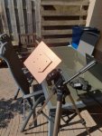
This is how I have to use it (rotated):

20200405_145810.jpg

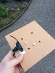
And this is the modification I made:

20200412_203607.jpg

No matter if I choose the LHCP or RHCP connector, I have to rotate the antenna so that the SMA connector at the back side is at 3 o'clock position for best signal..
 

dlwtrunked

Member
Premium Subscriber
Joined
Dec 19, 2002
Messages
2,128
The design I have has a slightly smaller square plate in front of the square plate with the corners cut off. That additional square plate is not electrically attached to the rest. I am still confused about the "3 o'clock position" as I do not know what that is relative to. Other dimension are somewhat different than yours--up to 10mm. This was bought some time back from Nooelec who no longer sell them (they got from elsewhere who stopped making them). I know someone who has made some copies and will try to get him into the thread.
 

Remon

Newbie
Joined
Jul 19, 2018
Messages
72
Location
The Netherlands
I think you mention the outernet air gap antenna. I want to duplicate that antenna and give it a try. Found all dimensions except for feed point of the patch itself (copied from thingverse comments):

Director: Aluminum, 3" x 3" x 0.02"
Driven element: Brass, 3.35" x 3.35" x 0.015" Corners cut at 2.00"
Reflector: Aluminum, 4.75" x 4.75" x 0.01"

Reflector to driven element: 0.25"
Driven element to director: 0.2"

Which converts roughly to:

Director: 76 x 76 mm
Patch: 85 x 85 mm (corners cut at 50 mm)
Reflector: 120 x 120 mm

Spacers between reflector and patch: 6.5 mm
Spacers between patch and director: 5 mm

I doubt this information is correctly because corners seems cut too deep compared from what I've seen from pictures of the actual outernet antenna.
 

Remon

Newbie
Joined
Jul 19, 2018
Messages
72
Location
The Netherlands
dlwtrunked: I still have a 300 x 200 mm pcb laying around, I could try the design of the antenna you're using. Are there any building plans on the internet?
 

prcguy

Member
Joined
Jun 30, 2006
Messages
15,344
Location
So Cal - Richardson, TX - Tewksbury, MA
I believe the patch antenna is not circular polarized but linear polarized, I would have to see the plans to be sure. It sounds like you are using a linear pol antenna to receive circular pol signals, which can sort of work but you will have up to 3dB degradation and the antenna will favor a certain rotation as you are seeing. If your antenna was actually circular pol you would see a huge difference going from right hand to left hand. Signals would be there on one pol and completely disappear on the other and you are not seeing that.

Circular polarity can be created in an antenna in several different ways. Sometimes with a pair of dipoles at 90 degrees and one is fed 90 degrees out of phase, or one is moved 90 degrees or about 1/4 wavelength in front of or behind the other. With horn and similar antennas you can delay the signals between two pickup probes with a dielectric card stuck in the feed ahead of the probes.

I don't see anything in the patch antenna here that would create circular pol. Is the second SMA connector simply adding another linear pol like horizontal?
 

Remon

Newbie
Joined
Jul 19, 2018
Messages
72
Location
The Netherlands
Thank you prcguy. Your post clarifies a lot to me.

Answer to your last question: yes it is, but I got exactly the same results and signal strength, even when the cuts are in the opposite corners by choosing the other connector.

This patch design antenna is widely used, praised and discussed all over the internet. I have seen people making a mirrored version when using together with a dish. I think it doesn't make sense to do that because it ain't a circular polarized antenna (they are still "advertised" as circular polarized antennas)..

Also, there are plenty of GPS antennas (some can be found real cheap on Chinese websites) that are being modified by removing the filter for use on other L-band satellites. Those have basically the same design: square patch with cut corners.
 

dlwtrunked

Member
Premium Subscriber
Joined
Dec 19, 2002
Messages
2,128
I have also tried the eBay item "RTL-SDR Blog Active L-Band 1525-1637 Inmarsat to Iridium Patch Antenna Set". For some reason, my full post did not go through. I do not think the the eBay antenna was as sensitive but it was some time back and my memory is not good on that.
 

dlwtrunked

Member
Premium Subscriber
Joined
Dec 19, 2002
Messages
2,128
Thank you prcguy. Your post clarifies a lot to me.

Answer to your last question: yes it is, but I got exactly the same results and signal strength, even when the cuts are in the opposite corners by choosing the other connector.

This patch design antenna is widely used, praised and discussed all over the internet. I have seen people making a mirrored version when using together with a dish. I think it doesn't make sense to do that because it ain't a circular polarized antenna (they are still "advertised" as circular polarized antennas)..

Also, there are plenty of GPS antennas (some can be found real cheap on Chinese websites) that are being modified by removing the filter for use on other L-band satellites. Those have basically the same design: square patch with cut corners.
I believe the patch antenna is not circular polarized but linear polarized, I would have to see the plans to be sure. It sounds like you are using a linear pol antenna to receive circular pol signals, which can sort of work but you will have up to 3dB degradation and the antenna will favor a certain rotation as you are seeing. If your antenna was actually circular pol you would see a huge difference going from right hand to left hand. Signals would be there on one pol and completely disappear on the other and you are not seeing that.

Circular polarity can be created in an antenna in several different ways. Sometimes with a pair of dipoles at 90 degrees and one is fed 90 degrees out of phase, or one is moved 90 degrees or about 1/4 wavelength in front of or behind the other. With horn and similar antennas you can delay the signals between two pickup probes with a dielectric card stuck in the feed ahead of the probes.

I don't see anything in the patch antenna here that would create circular pol. Is the second SMA connector simply adding another linear pol like horizontal?

The patch *is* circularly polarized. Note the feed point relative to the cut corners is not the same in a mirror.
 

Remon

Newbie
Joined
Jul 19, 2018
Messages
72
Location
The Netherlands
I just followed all build directions and it doesn't work like a circular pol antenna. I don't see what I might have missed while building it.

An unsubstantiated assumption: the director is neccessary to make it true circular polarized? So that the signal hits the one uncut corner and then the other uncut corner after. That might explain why a big part of the antenna is covered that way?
 

prcguy

Member
Joined
Jun 30, 2006
Messages
15,344
Location
So Cal - Richardson, TX - Tewksbury, MA
A director would give it more gain but the antenna part you have must be circular polarized to start with.

I just followed all build directions and it doesn't work like a circular pol antenna. I don't see what I might have missed while building it.

An unsubstantiated assumption: the director is neccessary to make it true circular polarized? So that the signal hits the one uncut corner and then the other uncut corner after. That might explain why a big part of the antenna is covered that way?
 

dlwtrunked

Member
Premium Subscriber
Joined
Dec 19, 2002
Messages
2,128
The patch antenna you built *is* circularly polarized (not linear) and is the standard "cut the corners" design. Note in a mirroir the difference where the feed is relative to the nearest cut corner--it will be different.
Ref.: https://arrow.tudublin.ie/cgi/viewcontent.cgi?article=1060&context=engdoc
As to why you do not see what should be expected, things that come to mind include:
1. Things are not quite properly measured to that the response of the antenna is not as desired at the frequencies you are tuning.
2. Antennas never work perfectly--surrounding reflections (which will change the circular polarization) and other factors.
I am sure there are other things. But beyond that I am puzzled. Also, it is not clear to me that a patch antenna, though circularly polarized, would not respond to some extent to circularly polarization int he other direction.
 
Last edited:

dlwtrunked

Member
Premium Subscriber
Joined
Dec 19, 2002
Messages
2,128
The design may have been intended to be circular pol but it sounds like the OPs antenna is not.
A director would give it more gain but the antenna part you have must be circular polarized to start with.

Agree. I accidently sent the earlier post before it was finished (which it is above). From looking at designs, some have a director and some do not. I am still puzzled by the "rotate it 90 degrees" I guess I need to see before/after photos with it on the tripod pointed at the satellite with him indicating in addition where that is in the sky.

Here I only play with 3 different bought patch antennas for INMARSAT--I will try to do a comparison. When I really want to receive INMARSAT, I have a 3 foot solid dish on a rugged tripod (in the bedroom) with a log-periodic (so I am loosing some of the gain by using linear instead of circular polarization) feed and a good LNA. It works better than any patch antenna that I have tried so I never actually compared the patch antennas.
 

Remon

Newbie
Joined
Jul 19, 2018
Messages
72
Location
The Netherlands
I can build a new one. To make sure:

98 x 98 mm patch, bottom left and top right corner cut off at 21 mm. Feed at center, 25 mm from bottom.
170 x 170 mm reflector
 

prcguy

Member
Joined
Jun 30, 2006
Messages
15,344
Location
So Cal - Richardson, TX - Tewksbury, MA
Right hand and left hand circular polarization are not compatible or interchangeable. Its like trying to stick a right hand threaded bolt into a left hand threaded hole, it doesn't go in. A right hand circular polarized signal will or should have a huge attenuation if being received by a left hand circular pol antenna.

Two things stand out in previous posts that tell me the antenna may not be circular polarity. The fact you can rotate it and change reception is one, a good circular pol antenna should not change when rotated. When the other connector was used, presumably left hand, there should be a lot of attenuation, 20db, 30db, etc and there was little change if any. That is not consistent with a circular pol antenna.

When you mention reflections its true that a reflection will swap circular polarity. Placing a circular pol antenna at the feedpoint of a reflector or dish will swap polarity, so if you use the patch antenna in front of a dish the patch would need to be left hand circular for the entire antenna with reflector to receive right hand circular.


The patch antenna you built *is* circularly polarized (not linear) and is the standard "cut the corners" design. Note in a mirroir the difference where the feed is relative to the nearest cut corner--it will be different.
Ref.: https://arrow.tudublin.ie/cgi/viewcontent.cgi?article=1060&context=engdoc
As to why you do not see what should be expected, things that come to mind include:
1. Things are not quite properly measured to that the response of the antenna is not as desired at the frequencies you are tuning.
2. Antennas never work perfectly--surrounding reflections (which will change the circular polarization) and other factors.
I am sure there are other things. But beyond that I am puzzled. Also, it is not clear to me that a patch antenna, though circularly polarized, would not respond to some extent to circularly polarization int he other direction.
 
Status
Not open for further replies.
Top