Newbie squelch question.

Status
Not open for further replies.

walterb

Member
Premium Subscriber
Joined
May 15, 2008
Messages
82
I turn my squelch all the way to to the point right before the white noise starts so its quiet, then a broadcast comes on, but after the broadcast is finished the white noise starts and doesn't stop until I turn my squelch knob farther away from the original "tipping point".

Am I doing something wrong? shouldn't the "tipping point" between silence and white noise remain constant (as long as atomospherics, antenna, etc doesn't change) ?? How does a broadcast effect that "tipping point" / adjustment?

thanks
 

gmclam

Member
Premium Subscriber
Joined
Sep 15, 2006
Messages
6,340
Location
Fair Oaks, CA
Squelch

There are a few variables with modern day squelch controls.

1. What scanner are you using?

2. Is this a "trunked" channel? Trunk tracking affects the squelch.

3. Do you have CT/DC tones enabled? When you do, reception of the programmed tone controls the squelch.
 

n2mdk

Member
Joined
Jul 27, 2007
Messages
2,450
Location
Ames, IA
It's an imperfect world, that does happen, just give it a little more squelch.
 

radiopro52

Member
Joined
Dec 27, 2007
Messages
261
Location
North Alabama
I usually have my squelch knob pointed up (half way) and I don't have any problems with noise. If you stop increasing the squelch when a broadcast comes on, it may still be a little low to block out radio static when the broadcast is done.
 

walterb

Member
Premium Subscriber
Joined
May 15, 2008
Messages
82
squelch

1. What scanner are you using?

Uniden SC230 Handheld

2. Is this a "trunked" channel? Trunk tracking affects the squelch.
No (Railroad and Police)

3. Do you have CT/DC tones enabled? When you do, reception of the programmed tone controls the squelch.
Unknown? Whats that? (told you it was a newbie question. )
 

RKG

Member
Joined
May 23, 2005
Messages
1,096
Location
Boston, MA
You have encountered the phenomenon of hysteresis. Just tighten the squelch a tad more. This is normal.
 

ScanTheFreqs

Completely Banned for the Greater Good
Banned
Joined
Apr 23, 2008
Messages
84
completely normal, just need to turn it up a little more
 

zz0468

QRT
Banned
Joined
Feb 6, 2007
Messages
6,034
RKG said:
You have encountered the phenomenon of hysteresis. Just tighten the squelch a tad more. This is normal.

And just to clarify, hysteresis is less a "phenomenon" and more of a design feature, and very much normal.
 

gmclam

Member
Premium Subscriber
Joined
Sep 15, 2006
Messages
6,340
Location
Fair Oaks, CA
Squelch, CT & DC

walterb said:
3. Do you have CT/DC tones enabled? When you do, reception of the programmed tone controls the squelch.
Unknown? Whats that? (told you it was a newbie question. )
If the only element you've programmed into the scanner is the main frequency (154.800 for example), then the squelch of the scanner opens when it detects a carrier on that frequency. Sometimes people program in a CT (also called PL) value (such as 100.0) or a DC (also called DPL) value (such as 076) in addition to the main carrier frequency. Note this feature is not available on all scanners. I'm not familiar with your model to know if it is or not. When one of these values are programmed, even when the scanner detects a carrier on the main frequency, the squelch is not opened. In this case the scanner must also detect this "sub-audible" value before it will open the squelch.

I've experience situations where there can be two signals on the same frequency, but each using different CT values, which causes interesting things with the squelch. I've also experienced where the CT/DC signal is on the edge of detection and makes the squelch toggle point marginal.

A little hysteresis on the squelch is good and normal as it keeps it from "motorboating" (rapidly turning on and off when the signal is at the threshold); but too much hysteresis makes the squelch awkward to adjust.
 

n1das

Member
Joined
Feb 17, 2003
Messages
1,601
Location
Nashua, NH
RKG said:
You have encountered the phenomenon of hysteresis. Just tighten the squelch a tad more. This is normal.

What I don't like is there tends to be way too much hysteresis designed into the squelch circuit. This often forces me to modify the squelch circuit by either removing or backing off the amount of hysteresis to tailor it to my liking. What I like best is there should be just enough hysteresis to keep the squelch more or less stable at the threshold and no more than that. Any more hysteresis gets in the way of reliably opening on a weak signal that's just barely above the threshold.

Here's a simple test you can try to test the effect of hysteresis:
1. Program in a NOAA weather frequency into an available channel in the scanner. Try to find one that's slightly weak and scratchy in your area but still readable. If there's no NOAA WX broadcast in your area (unlikely but still possible), find an active ham repeater in the 2m and 440 bands. You need a weak but still readable signal that's transmitting continously while you try this experiment.

2. Set the squelch all the way tight or somewhere in between the threshold and all the way tight and just below where it squelches out the weak broadcast you're listening to. Leave the squelch control set at this position. The squelch needs to be open and you need to listen to the weak signal. Instead of playing with the squelch adjustment, we'll be listening to the weak signal while we play with the received signal strength in the next steps.

3. Slowly and carefully decrease the level of signal being received by the scanner. If it's a handheld scanner, you can do this by moving the scanner and finding a "dead spot". The trick is to do this SLOWLY so you notice the signal getting noisier (weaker) and then the squelch eventually closes on the signal. Note the relative amount of noisiness (noise quieting level) of the signal when the squelch finally closes. DO NOT ADJUST THE SQUELCH CONTROL to open the squelch again. Leave the squelch control set where it is.

4. Slowly and carefully INCREASE the level of signal being received by the scanner. With a handheld scanner, slowly and carefully move out of the dead spot found earlier and note the amount of noise quieting heard on the signal when the squelch finally opens again.

5. Try moving in and out of the dead spot in the signal several times, trying different squelch settings. Note the relative amount of noise quieting level heard when the squelch closes on a fading signal and when the squelch finally opens again on the signal as it gets stronger again.

With scanners that have LOTS of hysteresis in the squelch circuit, the signal will have to get MUCH stronger than it was when the signal was fading out to where the squelch closed on the weak signal. I've seen some cases in a couple of scanners where the amount of hysteresis was so great that a signal would become almost all noise before the squelch would finally close and then wouldn't open again until the signal was nearly dead full quieting (DFQ) and very strong.

Where I've seen too much hysteresis be a problem is when there's a weak but still readable signal on a channel and the squelch would stay open on it if it were already open to begin with but it never opens because there's never enough signal to open it in the first place. This drives me nuts and eventually forces me to optimize the hysteresis in the circuit. The excessive amount of hysteresis gets in the way of reliable squelch operation.

I recall many old Regency scanners back in the 70's and 80's were designed with absolutely NO hysteresis whatsoever. What was good about these circuits was that if a signal was strong enough to be above the threshold, you heard it. If it was below the threshold, you didn't. The squelch would reliably hold open on a weak signal provided it stayed above the threshold level. The bad part was when a signal was weak and hovering around the threshold, causing the squech to constantly chatter or sputter or just crackle as the signal was just strong enough to partially crack it open. These squelch circuits could have been helped a lot by just a little bit of hysteresis...add in just enough to get rid of instability at the threshold but not enough to get in the way.

If you've got a scanner with NO hysteresis at all in the squelch, it will have no "dead zone" like a circuit with lots of hysteresis will. You'll notice the tendency to chatter or sputter open and closed as the weak signal hovers around the threshold.

I've found a lot of well designed 2-way radios have just enough hysteresis in their squelch circuits to get rid of the tendency to chatter at the threshold and NO MORE THAN THAT. The exact amount of hysteresis has been optimized for the particluar design. I've found from experience over the years that this is the amount of hysteresis I like best.
 
Last edited:

n1das

Member
Joined
Feb 17, 2003
Messages
1,601
Location
Nashua, NH
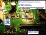
I'm resurrecting an old thread here....I've successfully optimized the squelch hysteresis in my BC785D and I think the mod should be identical on a BC796D. The modification involves changing one resistor to a higher value to reduce the amount of hysteresis feedback in the squelch circuit. Like in my above posts, sooner or later I end up modifying the squelch circuit in all of my scanners to optimize the amount of hysteresis for each design.

Uniden like GRE likes to design in 6 dB of hysteresis. I find this to be WAY TOO MUCH hysteresis for my liking. I've found from experience over the years that anything more than about 2 dB begins to be too much. The "sweet spot" I want is somehere in the 0-2 dB range.

In the BC785D, the resistor providing hysteresis feedback needs to be changed from 220k ohms to 1 Meg ohm or higher. I recommend trying 1Meg first and see how you like it. This should give you around 1 dB of hysteresis. If you still want less hysteresis and don't mind a little tendency to chatter at the threshold, increase the value to 2.2Meg. If you want absolutely no hysteresis at all like old Regency scanners had years ago (like the Regency Touch M100 for example), simply remove the resistor.

From testing with a weak signal fed into the scanner from a calibrated signal generator:

220k ohms --> 6 dB hysteresis
470k --> 2 dB
1Meg --> 1dB
2.2Meg --> 0.5 dB
Infinite (resistor removed) --> 0 dB

You may need to tweak the squelch gain pots afterward to get the squelch control's range of adjustment where you like it.

The attached JPG show the resistor location near IC8 on the main PCB. The mod should be the same on a BC796D since a 796D is basically an upgraded 785D. I don't have a 796D to verify it with but I would expect the squelch circuit to be identical and the board layout to be identical in this area. I also don't know the reference designator for the resistor because I don't have a schematic. I resorted to using a sig gen to feed a weak signal into the scanner while probing around with a voltmeter in the squelch circuit to find the correct resistor to change.
 

Attachments

  • N1DAS_BC785D_sq_hysteresis.jpg
    N1DAS_BC785D_sq_hysteresis.jpg
    110.2 KB · Views: 7,701
Last edited:

gewecke

Completely Banned for the Greater Good
Banned
Joined
Jan 29, 2006
Messages
7,452
Location
Illinois
I'm resurrecting an old thread here....I've successfully optimized the squelch hysteresis in my BC785D and I think the mod should be identical on a BC796D. The modification involves changing one resistor to a higher value to reduce the amount of hysteresis feedback in the squelch circuit. Like in my above posts, sooner or later I end up modifying the squelch circuit in all of my scanners to optimize the amount of hysteresis for each design.

Uniden like GRE likes to design in 6 dB of hysteresis. I find this to be WAY TOO MUCH hysteresis for my liking. I've found from experience over the years that anything more than about 2 dB begins to be too much. The "sweet spot" I want is somehere in the 0-2 dB range.

In the BC785D, the resistor providing hysteresis feedback needs to be changed from 220k ohms to 1 Meg ohm or higher. I recommend trying 1Meg first and see how you like it. This should give you around 1 dB of hysteresis. If you still want less hysteresis and don't mind a little tendency to chatter at the threshold, increase the value to 2.2Meg. If you want absolutely no hysteresis at all like old Regency scanners had years ago (like the Regency Touch M100 for example), simply remove the resistor.

From testing with a weak signal fed into the scanner from a calibrated signal generator:

220k ohms --> 6 dB hysteresis
470k --> 2 dB
1Meg --> 1dB
2.2Meg --> 0.5 dB
Infinite (resistor removed) --> 0 dB

You may need to tweak the squelch gain pots afterward to get the squelch control's range of adjustment where you like it.

The attached JPG show the resistor location near IC8 on the main PCB. The mod should be the same on a BC796D since a 796D is basically an upgraded 785D. I don't have a 796D to verify it with but I would expect the squelch circuit to be identical and the board layout to be identical in this area. I also don't know the reference designator for the resistor because I don't have a schematic. I resorted to using a sig gen to feed a weak signal into the scanner while probing around with a voltmeter in the squelch circuit to find the correct resistor to change.

Dave do you think this mod might apply to the 780xlt as well?
Thanks.
n9zas
 

n1das

Member
Joined
Feb 17, 2003
Messages
1,601
Location
Nashua, NH
Dave do you think this mod might apply to the 780xlt as well?
Thanks.
n9zas

The same mod might apply to 780 but I can't say for sure because I don't have one and I don't have any schematics. You may have to experiment and probe around like I did to find it. Also, the trimpots on the board may be in different locations and do different things. I'm speculating here because I don't have one to look at.

There IS hysteresis feedback in the squelch circuit in all of Uniden's designs, so the same sort of mod would apply but it may be a different resistor value and in a different location. Since the 785D and 796D designs evolved from the 780's design, I would expect the schematic and board layout to be similar.

It $uck$ that schematics aren't readily available due to the cell phone frequency censorship.
 

gewecke

Completely Banned for the Greater Good
Banned
Joined
Jan 29, 2006
Messages
7,452
Location
Illinois
The same mod might apply to 780 but I can't say for sure because I don't have one and I don't have any schematics. You may have to experiment and probe around like I did to find it. Also, the trimpots on the board may be in different locations and do different things. I'm speculating here because I don't have one to look at.

There IS hysteresis feedback in the squelch circuit in all of Uniden's designs, so the same sort of mod would apply but it may be a different resistor value and in a different location. Since the 785D and 796D designs evolved from the 780's design, I would expect the schematic and board layout to be similar.

It $uck$ that schematics aren't readily available due to the cell phone frequency censorship.

Exactly what I was thinking, that the hardware and schematic design in the 780 is close enough that maybe some "creative dinkin" with some probes and a VOM might produce some ideas!
Thanks again.
n9zas
 

n1das

Member
Joined
Feb 17, 2003
Messages
1,601
Location
Nashua, NH
PSR-600 next on my list

My GRE PSR-600 is next on my list to optimize the amount of hysteresis in the squelch circuit. It also has too much hysteresis like Unidens typically have. 6 dB of hysteresis as designed is way too much for my liking. I'll post my results and mod info in the GRE scanners forum section.
 
Last edited:

n1das

Member
Joined
Feb 17, 2003
Messages
1,601
Location
Nashua, NH
I'm resurrecting an old thread here....I've successfully optimized the squelch hysteresis in my BC785D and I think the mod should be identical on a BC796D. The modification involves changing one resistor to a higher value to reduce the amount of hysteresis feedback in the squelch circuit. Like in my above posts, sooner or later I end up modifying the squelch circuit in all of my scanners to optimize the amount of hysteresis for each design.

Uniden like GRE likes to design in 6 dB of hysteresis. I find this to be WAY TOO MUCH hysteresis for my liking. I've found from experience over the years that anything more than about 2 dB begins to be too much. The "sweet spot" I want is somehere in the 0-2 dB range.

In the BC785D, the resistor providing hysteresis feedback needs to be changed from 220k ohms to 1 Meg ohm or higher. I recommend trying 1Meg first and see how you like it. This should give you around 1 dB of hysteresis. If you still want less hysteresis and don't mind a little tendency to chatter at the threshold, increase the value to 2.2Meg. If you want absolutely no hysteresis at all like old Regency scanners had years ago (like the Regency Touch M100 for example), simply remove the resistor.

From testing with a weak signal fed into the scanner from a calibrated signal generator:

220k ohms --> 6 dB hysteresis
470k --> 2 dB
1Meg --> 1dB
2.2Meg --> 0.5 dB
Infinite (resistor removed) --> 0 dB

You may need to tweak the squelch gain pots afterward to get the squelch control's range of adjustment where you like it.

The attached JPG show the resistor location near IC8 on the main PCB. The mod should be the same on a BC796D since a 796D is basically an upgraded 785D. I don't have a 796D to verify it with but I would expect the squelch circuit to be identical and the board layout to be identical in this area. I also don't know the reference designator for the resistor because I don't have a schematic. I resorted to using a sig gen to feed a weak signal into the scanner while probing around with a voltmeter in the squelch circuit to find the correct resistor to change.

Anybody tried this mod yet on a BC796D ???
 
Status
Not open for further replies.
Top