Like has been said. You should really remove one leg of the resistor to test it. You can have another component in parallel with the resistor somewhere else in the circuit that can make for inaccurate readings.

-
To anyone looking to acquire commercial radio programming software:
Please do not make requests for copies of radio programming software which is sold (or was sold) by the manufacturer for any monetary value. All requests will be deleted and a forum infraction issued. Making a request such as this is attempting to engage in software piracy and this forum cannot be involved or associated with this activity. The same goes for any private transaction via Private Message. Even if you attempt to engage in this activity in PM's we will still enforce the forum rules. Your PM's are not private and the administration has the right to read them if there's a hint to criminal activity.
If you are having trouble legally obtaining software please state so. We do not want any hurt feelings when your vague post is mistaken for a free request. It is YOUR responsibility to properly word your request.
To obtain Motorola software see the Sticky in the Motorola forum.
The various other vendors often permit their dealers to sell the software online (i.e., Kenwood). Please use Google or some other search engine to find a dealer that sells the software. Typically each series or individual radio requires its own software package. Often the Kenwood software is less than $100 so don't be a cheapskate; just purchase it.
For M/A Com/Harris/GE, etc: there are two software packages that program all current and past radios. One package is for conventional programming and the other for trunked programming. The trunked package is in upwards of $2,500. The conventional package is more reasonable though is still several hundred dollars. The benefit is you do not need multiple versions for each radio (unlike Motorola).
This is a large and very visible forum. We cannot jeopardize the ability to provide the RadioReference services by allowing this activity to occur. Please respect this.
You are using an out of date browser. It may not display this or other websites correctly.
You should upgrade or use an alternative browser.
You should upgrade or use an alternative browser.
Palomar 225 amp with a smoking resistor
- Thread starter AronDouglas
- Start date
- Status
- Not open for further replies.
prcguy
Member
An orange black orange gold resistor would be 30,000 ohms, 5% tolerance. If its reading 106 ohms on a meter its probably a brown black brown, which would be 100ohms.
prcguy
prcguy
I'm testing resistors tonight and I've tested 6 so far and I cant get a reading. I get a spike at first then it goes blank. I'm using a Fieldpiece LT17 meter (really good meter, its my dads hes had for years and hes an AC tech). I tested around till I got around to a 100Ohm (orange black orange, gold) and I get 106 on the meter. So I went back and tested the others and they are still blank.
Like has been said. You should really remove one leg of the resistor to test it. You can have another component in parallel with the resistor somewhere else in the circuit that can make for inaccurate readings.
I have, thats why I'm confused. I even took one completely out.
. Ok yah, that makes sense. I keep looking at glossy and flat colored resistors and some browns look like oranges. lol.If its reading 106 ohms on a meter its probably a brown black brown, which would be 100ohms.
Edit: You know what works good, the proper settings
") I was operating on Ohm, not KOhm
I was operating on Ohm, not KOhm
Last edited:
RC286
Member
Weird that its dropping out the reading like that especially with the resistor completely removed.
There a bad connection in one of the test leads?
Not familiar with this meter but it looks similar in operation to my meterman manual rage meter.
If your getting 106 ohms. that resistor is bang on, (well 6% out but your meters accuracy is +/- 1%+4R between 200R and 200K, it is +/-2%+4R between in the 20M range this is on top of the resistor tolerance)
I don't think you will find a dead or drifted resistor. I have been servicing electronics as a hobby for over 12yrs. Even restored radios as vintage as 1930's and in those 12yrs I have only ever found ONE resistor that was bad.
Now, your saying that when you switch on the pre amp the TX LED comes on?
Now I cant say for sure as the schematic we are going by is a reference, but comparing it, my amp, and any other palomar amp I have seen in this size/wattage range, the third LED is not for high/low power, it
lights up when the amp senses a carrier and switches over to power output to amplify the signal. This is
still not normal operation, that LED should not light up until the attached radio is keyed up.
stranger yet, in the schematic I see no interaction between that switch and the circuits that control the
RF preamp or sensing bridge network. All it does is switch in a 43R 2W resistor to create a voltage divider between it and the 9.1R 2W resistor to create a rudimentary attenuator.
Do you have any internal pictures depicting how your wired up your new switches and LEDs?
I cleaned the resistors in question and changed my meter over to KOhm and retested them with success.
Ok, here is the face place and its original switches. The plate is orientated correctly to the switches as well. Give me about 20-30 min and I can have the other switches back on.

Here is an inside look. Top right is the diode that I burnt up and replaced. Ignore the antenna connectors for right now

I still have the LEDs wired up with wires. Originally the LED bulb leads would go directly to the board. But since I changed the orientation of the switches and made a new face plate, I needed the extra length for the bulbs.
Pre-amp

Low-off-high

Amp pwr

Edit: And here is the aftermarket switches. You can try to decipher the wiring if you want (or just request more pictures). All I did was put wires in place of direct switch contact. (I used solid core 18 gauge wire). And all I did was switch the Pre amp and Low-off-high switch around.


Ok, here is the face place and its original switches. The plate is orientated correctly to the switches as well. Give me about 20-30 min and I can have the other switches back on.
Here is an inside look. Top right is the diode that I burnt up and replaced. Ignore the antenna connectors for right now
I still have the LEDs wired up with wires. Originally the LED bulb leads would go directly to the board. But since I changed the orientation of the switches and made a new face plate, I needed the extra length for the bulbs.
Pre-amp
Low-off-high
Amp pwr
Edit: And here is the aftermarket switches. You can try to decipher the wiring if you want (or just request more pictures). All I did was put wires in place of direct switch contact. (I used solid core 18 gauge wire). And all I did was switch the Pre amp and Low-off-high switch around.
Last edited:
RC286
Member
I am assuming the LEDs are in the same order as they were on the original amp faceplate? (i noticed you
re-located the position of 2 switches, but were the 2 LEDs re-located as well?)
If that's the case
Left should be power indicator
Middle should be TX indicator'
Right should be Pre amp indicator
I don't see anything jumping out at me saying you wired anything wrong so we'll assume that its correct for now.
Do you have a picture of the underside of the circuit board?
Also a note for the final assembly. make sure when you re assemble the heat-sink to the finals once this thing is working, that you clean up the surfaces and use some good quality heat-sink compound on the finals.
EDIT: NVM i started posting this before I saw your new switch/led wiring.
As far as i see in the new wiring it looks the same just re-located.
Last edited:
RC286
Member
I'm thinking you have a couple bad transistors.
Do you have a pic of the underside of the board?
Might be able to trace out the likely culprits.
Do you have a pic of the underside of the board?
Might be able to trace out the likely culprits.
Oh trust me, I know what can go wrong with a bad thermal paste job Being paranoid as hell over pasting a CPU on wrong tend to make on REALLY good really fast


Being paranoid as hell over pasting a CPU on wrong tend to make on REALLY good really fast
Sorry, I missed it when you said you wanted more detailed pics of the transistors. (I assume you meant these two and not the other two smaller ones, the 2N3904s)
The scratches are from when I removed the negative side of the power line and replaced it with thicker wire.


And while we're on this topic, what up with this amp? Its a Palomar 350. Specifically the connecting wire that connects the two transistors.

The scratches are from when I removed the negative side of the power line and replaced it with thicker wire.
And while we're on this topic, what up with this amp? Its a Palomar 350. Specifically the connecting wire that connects the two transistors.
Last edited:
RC286
Member
Think I MAY have figured it out.
The amp looks more similar to this
http://www.cbtricks.com/Amp/palomar_other/blue_lightning/graphics/blue_lighting_sch.pdf
The difference being the 2N3906 was replaced with a 2N3904 and support circuitry for the sensing of the
RF carrier. If I am correct. Then I am assuming the transistor in your amp near the big coil has shorted.
(Do you hear a relay kick in when you power it up with the RF preamp off?)
If yes then this may be the solution.
With the power selector switch in the mid position it is floating, and when the preamp is powered, it isolates
the entire antenna circuit. This also activates the preamp with no load. Unloaded high impedance
amplifiers have a nasty habit of going into oscillation if they are not loaded. This generates RF.
The TX LED by the look of it being decoupled by a capacitor, is excited by RF, the snubber diode before it
protects the LED from reverse voltage by shunting the negative waveform and only letting the positive
through. The close proximity of the lines from the preamp in the relay to the leads of the now unloaded
power amp, have a capacitive coupling effect that cause the power amp to become excited, although
slightly, generate enough RF to excite the LED.
Now when you switch the power switch to either side, it loads the circuit with the low resistance resistor
designed to attenuate the signal. This shunts the tiny bit of RF from the preamp to ground preventing it
from exciting the power amp enough to light the LED.
Pull that transistor and test it. I am about 80% sure it will be dead.
Isn't RF fun haha!
PS. to answer your question on the last pic.
1. the braid is for extra RF shielding, it creates a good RF ground across the transistors. Is it needed,
probably not, but it is common practice in some amps. Mine has it. It was probably a design improvement
added later on.
2. the circled capacitor is a delay capacitor added for SSB. this is a mod. And probably so was the braid.
It is the delay cap I mentioned in my first post.
Try checking that transistor and hopefully this will be the solution.
Cheers.
Good luck and 73's
EDIT:
I forgot the crucial link, the output of the power amp, that has no amplified the low RF feeds back into the SAME relay with more than likely
enough capacitive coupling to feed into the circuit and light the LED. It is also putting this out into the antenna port. If you have access to a meter, scope or
frequency counter to check the frequency, I bet you if you put one lead in the antenna socket and hold the other to the shielded threads, you will get a reading
of the probably unstable frequency your giant oscillator is producing.
The amp looks more similar to this
http://www.cbtricks.com/Amp/palomar_other/blue_lightning/graphics/blue_lighting_sch.pdf
The difference being the 2N3906 was replaced with a 2N3904 and support circuitry for the sensing of the
RF carrier. If I am correct. Then I am assuming the transistor in your amp near the big coil has shorted.
(Do you hear a relay kick in when you power it up with the RF preamp off?)
If yes then this may be the solution.
With the power selector switch in the mid position it is floating, and when the preamp is powered, it isolates
the entire antenna circuit. This also activates the preamp with no load. Unloaded high impedance
amplifiers have a nasty habit of going into oscillation if they are not loaded. This generates RF.
The TX LED by the look of it being decoupled by a capacitor, is excited by RF, the snubber diode before it
protects the LED from reverse voltage by shunting the negative waveform and only letting the positive
through. The close proximity of the lines from the preamp in the relay to the leads of the now unloaded
power amp, have a capacitive coupling effect that cause the power amp to become excited, although
slightly, generate enough RF to excite the LED.
Now when you switch the power switch to either side, it loads the circuit with the low resistance resistor
designed to attenuate the signal. This shunts the tiny bit of RF from the preamp to ground preventing it
from exciting the power amp enough to light the LED.
Pull that transistor and test it. I am about 80% sure it will be dead.
Isn't RF fun
haha!PS. to answer your question on the last pic.
1. the braid is for extra RF shielding, it creates a good RF ground across the transistors. Is it needed,
probably not, but it is common practice in some amps. Mine has it. It was probably a design improvement
added later on.
2. the circled capacitor is a delay capacitor added for SSB. this is a mod. And probably so was the braid.
It is the delay cap I mentioned in my first post.
Try checking that transistor and hopefully this will be the solution.
Cheers.
Good luck and 73's
EDIT:
I forgot the crucial link, the output of the power amp, that has no amplified the low RF feeds back into the SAME relay with more than likely
enough capacitive coupling to feed into the circuit and light the LED. It is also putting this out into the antenna port. If you have access to a meter, scope or
frequency counter to check the frequency, I bet you if you put one lead in the antenna socket and hold the other to the shielded threads, you will get a reading
of the probably unstable frequency your giant oscillator is producing.
Last edited:
Are you talking about the "pills" transistors or the 2 small transistors?
Ok, as it is 0125 my time, 90% of what you said went right over my head. But its nothing a good nights rest and a few cups of coffee cant fix.
I only hear the relay click (not sure which relay it is yet) when the amp is on and the I flip the pre amp. If I flip the pre-amp by itself I dont hear anything. And to make matters more fun, I only get 1 LED to come on now...the high-low LED....thats with amp and pre-amp on.
Ok, 4th times the charm. I understood what your troubleshooting and I'll test the transistor.
If you look back, I have the "red circled cap" on my amp as well (I didn't circle the cap, I just pulled the pic from some google search). And should I add the braided RF ground?
Last edited:
Ok, the small transistor ( 2N3904 near the coil) reads .694 and .673. And I am reading similar on the other one near the switches. But I'm guessing your wanted my to check the "pills".
RC286
Member
I did notice, and if the schematic is accurate enough, it looks like a delay capacitor that was installed but not connected to anything. C12 in the schematic I posted, notice it has NC on the other lead.
If you decide to add SSB delay, it is easier to just tack a capacitor across the snubbing diode on the relay coil. I can help you with that later if you desire, right now we will concentrate on getting this thing doing
its proper thing.
The transistor I am referring to is the small one. In your amp, you said you had 2N3904s.
The one I am talking about is in the top left corner when viewed with the switches facing you.
It is the one in between the two relays and the funny coil and the antenna transmitter coax connector.
I wouldn't bother with the braid, if you get the amp working, and its working fine, I wouldn't worry
about the hassle.
To hear the relay kick in, you may need to leave the power switch on, and connect connect it to the battery as the sound of the switch might drown out the relay.
That said, if the transistor checks out fine, the relay could very well be stuck in the TX position.
I can walk you through how to test that without taking it off the board.
My dads an AC tech and we've seen some weird things happen to relays. Once we applied AC to a DC relay just to see what would happen I was discussing the amp with my friend a few days ago and I mentioned the relays and how I heard it engage. He entertained the idea of a faulty/stuck relay as well. So far the faulty relay idea has come up between 3 different people.
And so far teh transistor checks out. I've gota dig up the data sheet and double check though.
I was discussing the amp with my friend a few days ago and I mentioned the relays and how I heard it engage. He entertained the idea of a faulty/stuck relay as well. So far the faulty relay idea has come up between 3 different people.And so far teh transistor checks out. I've gota dig up the data sheet and double check though.
RC286
Member
Yep the transistor sounds pretty close to where it should be.
I would suspect it to be okay.
Give me a sec, i'll edit your pic and show you where to meter to test that relay.
I would suspect it to be okay.
Give me a sec, i'll edit your pic and show you where to meter to test that relay.
RC286
Member
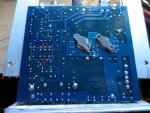
I attached the image.
The use the ohms scale and measure between the two pins on the two sets shown in red.
the relay foot print is circled in yellow.
The far lonely pins are the coil.
The ones your measuring are between the common and normally open.
When the relay is not active, you should get complete isolation, however if the contacts stuck closed
you should get close to 0 ohms.
Attachments
I have no continuity (0L) between the points you showed to check. But occasionally, if I breath right, I can get a short connection. Since a relay is a mechanical device, perhaps this relay is failing but just strong enough to operate normal under no load. I have seen this happen before, and it can cause quite a headache when troubleshooting. Its hard to pin point something when it functions properly 90% of the time
Last edited:
RC286
Member
Yeah relays can be finicky, as can the glaze that manufactures put on their boards, if this board has a protective glaze, it may be making it hard to get a good connection.
Another thing you can try is tapping on the top of the relay a few times with the blunt end of a screwdriver and see if it will release.
Power the amp and see if the LED situation still exists.
Another thing you can try is tapping on the top of the relay a few times with the blunt end of a screwdriver and see if it will release.
Power the amp and see if the LED situation still exists.
Problem still remains sadly. I did try tapping on it and flipping the board around, but I couldn't get it to make connection again.
A few days ago I found replacement relays and I considered getting new ones. Maybe I'll just spend the $10 and get a pair of them just to eliminate the possibility. And worst case, I spend money on an amp that has bad "pills". In which case I'll order some new ones since they are they are around the same price as a new amp anyways.
Well sir you have been a GREAT help and I thank you. I am NOT quitting yet, but I do have work in a few hours, so I must go. I apologize for keeping you up so late as well. I will be back as soon as possible to resume work on this thing. Again, thank you very much for your help.
prcguy
Member
You can test relays, just google the part # and you will get a pinout and specs. You can then measure the coil resistance, apply 12v to the coil and measure for contact closure and working or open contacts.
On the subject of "pills", they are referred to as RF PA (power amplifier) transistors or by other industry accepted terminology. If you are within earshot of someone who actually knows what they are and works with them and you call them pills, watch for their eyes to roll backwards.
Calling an RF PA transistor a "pill" to someone in the RF industry (and I don't mean CB radio amplifier hackers) is like discussing the automatic transmission in your car with a transmission specialist and calling it a "swishey thingee" or other silly pet name. I suspect if you call up a major parts supplier like RF Parts and ask for pills you'll hear laughter in the background as they prepare to take your money.
prcguy
Problem still remains sadly. I did try tapping on it and flipping the board around, but I couldn't get it to make connection again.
A few days ago I found replacement relays and I considered getting new ones. Maybe I'll just spend the $10 and get a pair of them just to eliminate the possibility. And worst case, I spend money on an amp that has bad "pills". In which case I'll order some new ones since they are they are around the same price as a new amp anyways.
Well sir you have been a GREAT help and I thank you. I am NOT quitting yet, but I do have work in a few hours, so I must go. I apologize for keeping you up so late as well. I will be back as soon as possible to resume work on this thing. Again, thank you very much for your help.
- Status
- Not open for further replies.
Similar threads
- Replies
- 19
- Views
- 3K