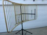
I was given a Kathrein/Scala UHF Paraflector antenna after a TV station rebuild I worked on and the antenna was tuned to around 524MHz. I wanted to modify the feed to work within the 70cm amateur band until I noticed it was a custom 75 ohm feed and not 50 ohms. Rats! These antennas are about the best you can get for UHF with 15.5dBd gain across 20MHz or more frequency range and they are made for most frequencies from 450MHz through 960MHz at a cost of $1500 on up. These are not corner reflector types but rather a thin slice of a parabola.
Anyway, I rummaged around my garage and found a chunk of aluminum pipe the same OD and length as the original feed and carefully made an entire new dipole with reflector with all connections inside the pipe similar to the original. I had never made a dipole feed with all the guts inside a small diameter pipe before and this created some technical challenges. I settled on using 5/16" diameter elements for the driven elements with the coax soldered to copper nuts as the interface to the elements which I threaded.
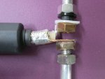
I used RG-214 silver plated double shielded coax to connect the dipole and provide a pigtal out the back of the antenna. RG-214 will provide a good mechanical connection to the dipole elements with a lot of surface area to take mechanical stress. I radiused the copper nuts to mate with the inside of the feed support pipe. The grounded side of the dipole would simply connect to the braid of the coax right at the element/ pipe junction but the hot side of the dipole will have to be insulated. I used a 5/16 nylon shoulder washer where the hot element goes through the pipe and a large nylon flat washer to insulate the copper nut inside the pipe connected to the coax hot.
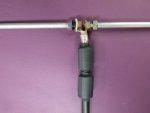
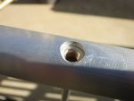
When soldering the copper nuts to the coax I used some copper sheet to mate the coax braid to the nut and the coax center conductor solders direct to the other copper nut. Before soldering, I had screwed both nuts onto a 5/16 bolt to space them the same as the pipe ID so the dipole feedpoint could be slid up into the pipe and keep its shape. This worked out great and you can see in one of the pictures how the dipole hot side nut sits perfectly centered below the hole in the support pipe with the white nylon insulator in just the right spot. All copper/aluminum interfaces got a thin coating of Burndy Penetrox to reduce dissimilar metal interaction. I also took apart two snap on ferrites and placed them near the feedpoint to help decouple the feedline from the driven elements. These ferrites barely fit inside the support pipe and three would have been nice but I only had two.
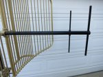
Feed element lengths and spacing were determined by calculating up the size of the original feed made for roughly 524Mhz. The new feed tuned up very well in the 440-450MHz range and has a useable match up to about 465MHz. The reflector is huge at about 6ft wide and 3ft tall and its gold anodizing looks good against the black paint job I gave the new feed. Now what to do with this beast????
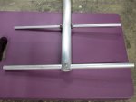
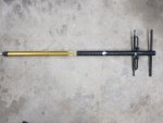
Here are some pictures of the feed details, the completed antenna and what the original 524MHz feed looked like.


