N3FAH
Member
WARNING: This post contains graphic descriptions and images of the internal organs of a radio that are not suitable for the faint-of-heart. ")
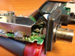
Recently my Pro-106 lost sensitivity (again), at first It lost just digital, but the longer I listened, the more stations dropped out. Finally I could hear only very strong and/or very close stations. After a week of agony thinking it was toast, I decided to open the box and have a look. (This is where the squeamish should tune out.) The main logic board is on top, it contains the RF and IF sections, the scan logic, etc. And the antenna jack - the BNC connector, mounts here. The RF section is shielded in a steel "can", but there are a couple of holes that you can peek through. If you peek in with a flashlight, you can see where the center pin of the BNC comes out on the chassis end. There is a little 1/8" loop of wire that comes up from the PC board and makes a half-turn around the BNC pin and is soldered there.
Given enough antenna swaps, the center conductor of the BNC will work back and forth until the solder joint breaks. That's when the sensitivity starts to decline. Hey... if the signal can make it thirty miles from the transmitter to the antenna, you'd think it could jump one more little 1/64" gap, wouldn't you? You'd be wrong. (Sorry, don't take it personally.) With the back cover off, and the radio on house power and scanning, use a thin NON-CONDUCTIVE plastic probe to -very gently- poke through the top gap on the inboard side of the shield 'til you can touch the wire from the PC board to the BNC - if the wire moves, and the signal strength improves -dramatically- you have found your culprit. (look for the attached photo.)
You'll have to re-solder that connection. With all POWER REMOVED, CAREFULLY peel up the top outboard corner of the shield. I snipped back the shield a little more to get my solder iron in there. Slide a strip of thin cardboard or heavy paper under the joint to protect the circuit board from "oopsies" and re-solder the antenna wire to the BNC. Remove the paper, blow out the 'can' to remove any debris. Bend the shield gently back in place being careful not to short anything, reassemble and you're done.
This is the second time I have had to do this. Analog FM signals are very forgiving - there are strong stations, and weak stations, but you can (usually) hear what's being said. Digital signals, on the other have, are essentially "all or nothing". If you don''t have a strong enough signal, either it "pixellates" and breaks the signal into undecipherable 1s and 0s; or the radio doesn't even see the signal at all. And if you swap the radio like I do from rooftop antenna to rubber ducky to car antenna... well, there goes the BNC. (OK, I hear ya, I brought it on myself. But hey, I fixed it too. And one "attaboy" wipes out a bunch of "aw $&#@s", right?)
Anyway, sorry for the lloonngg post but gotta get it all in one place. Good luck. N3FAH