datashifter
Newbie
I would like to preface this posting with "I am not looking to cause my scanner to receive frequencies or communications which are illegal to monitor."
That being said, I purchased a Pro-433 scanner yesterday evening. It was on clearance at the RatShack for $119.99 + tax. It's the first trunking scanner I've owned, and the only other scanner I own is a RatShack Pro-46.
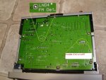
Today I cracked open my Pro-433 to inspect the test point which user "kd5dga" on this site posted as being a convenient discriminator tap point, labelled as LND4 FM Det. The post I'm refering to is located here - http://www.radioreference.com/forums/showthread.php?t=93667
While I was under the scanner's cover, I noted some key points of interest.
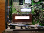
If I have learned anything over my decades of exploring electronics, it would be that anything underneath a black epoxy or plastic blob is typically something which the manufacturer really does not want you to tamper with. Well, there are three black blobs, under which several surface mount transistors, diodes, resistors, and capacitors appear to reside. Interesting stuff for later exploration, but for now the blobs will remain in place on my unit. I have no other trunking scanner, and I do not care to brick my scanner within the first few days of owning it by screwing something up as I scrape away the blobs - although the RatShack does have that wonderful 30 day return policy!
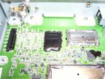
Also of interest is what appears to be an unpopulated 10-pin JTAG or UART header on the main circuit board.
Has anyone played around with the possible JTAG or UART interface on the board yet? I cannot visually the follow circuit traces from the pads to any chips, as the circuit traces are embedded within the PCB's inner layers.
I'm asking if anyone has played around with these areas on the board, as it would kind of suck to reinvent the wheel if someone has already been there and done this.
Attached are images depicting the convenient discriminator tap point (labelled as LND4 FM Det.), the potential JTAG/UART interface, and the black blobs.
I anxiously await any replies.
That being said, I purchased a Pro-433 scanner yesterday evening. It was on clearance at the RatShack for $119.99 + tax. It's the first trunking scanner I've owned, and the only other scanner I own is a RatShack Pro-46.
Today I cracked open my Pro-433 to inspect the test point which user "kd5dga" on this site posted as being a convenient discriminator tap point, labelled as LND4 FM Det. The post I'm refering to is located here - http://www.radioreference.com/forums/showthread.php?t=93667
While I was under the scanner's cover, I noted some key points of interest.
If I have learned anything over my decades of exploring electronics, it would be that anything underneath a black epoxy or plastic blob is typically something which the manufacturer really does not want you to tamper with. Well, there are three black blobs, under which several surface mount transistors, diodes, resistors, and capacitors appear to reside. Interesting stuff for later exploration, but for now the blobs will remain in place on my unit. I have no other trunking scanner, and I do not care to brick my scanner within the first few days of owning it by screwing something up as I scrape away the blobs - although the RatShack does have that wonderful 30 day return policy!
Also of interest is what appears to be an unpopulated 10-pin JTAG or UART header on the main circuit board.
Has anyone played around with the possible JTAG or UART interface on the board yet? I cannot visually the follow circuit traces from the pads to any chips, as the circuit traces are embedded within the PCB's inner layers.
I'm asking if anyone has played around with these areas on the board, as it would kind of suck to reinvent the wheel if someone has already been there and done this.
Attached are images depicting the convenient discriminator tap point (labelled as LND4 FM Det.), the potential JTAG/UART interface, and the black blobs.
I anxiously await any replies.