Phil_KD0SCJ
Member
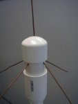
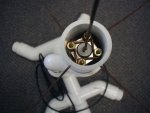
I recently made a prototype of the following antenna for receiving UHF/VHF, and it is performing very well for me. However, my prototype was made from a BNC connector and used 16 gauge copper (stuff I had lying around). I have now gathered the parts for a more permanent version. The SO-239 has a larger solder cup, allowing me to use larger copper wire. So, before I run this thing up a 30 foot mast, I have a question:
The drawing is not to scale otherwise you might wonder this yourself... The 19" vertical and other vertical elements are supported only by the solder connection at the SO-239. I am in Northern Minnesota, and this antenna will see significant wind, snow and occasional ice loads. My gut tells me I need to reinforce that solder joint in some way. I am thinking about encapsulating the area in green with a block of epoxy (clear, non-conducting, of course). In order to be effective, it will have to come up past the bottom of the 450MHz element. Maybe this will impact reception on the 70cm band, but I'm ok with that because the 70cm band is pretty quiet where I am anyway. Does anyone see any other pitfalls or have other solutions for this?
Yes, I could try it and see. I fully believe in the experimental find-out for yourself philosophy. I just can't undo epoxy so if this is a dumb idea, I'd really like to find out from people with more experience. And, bringing a 30 foot mast down for repairs in the winter here is just not a fun learning experience.
Yes, I have searched the forum and the internet on this. I couldn't find anything definitive, although there is mention of using epoxy to pot RF circuits, so that's why I chose epoxy as a candidate.
I am not transmitting with this antenna, and I can tolerate a minor reduction in signal. Actually, my prototype is at 10' and this will be at 30' so the net will probably still be a gain.
What else can I tell you... RG6 for cable to a pair of RTL-SDR's. (Trunking/P25 plus UHF/VHF exploration). Here is the antenna:

You can view the entire antenna at http://debandphil.com/pictures/ham/coathanger_antenna.pdf.
I found this quite some time ago, and I wish I had noted the source. I have gone back and tried to find it again, but no luck so far.
Thanks for your comments!
~Phil
The drawing is not to scale otherwise you might wonder this yourself... The 19" vertical and other vertical elements are supported only by the solder connection at the SO-239. I am in Northern Minnesota, and this antenna will see significant wind, snow and occasional ice loads. My gut tells me I need to reinforce that solder joint in some way. I am thinking about encapsulating the area in green with a block of epoxy (clear, non-conducting, of course). In order to be effective, it will have to come up past the bottom of the 450MHz element. Maybe this will impact reception on the 70cm band, but I'm ok with that because the 70cm band is pretty quiet where I am anyway. Does anyone see any other pitfalls or have other solutions for this?
Yes, I could try it and see. I fully believe in the experimental find-out for yourself philosophy. I just can't undo epoxy so if this is a dumb idea, I'd really like to find out from people with more experience. And, bringing a 30 foot mast down for repairs in the winter here is just not a fun learning experience.
Yes, I have searched the forum and the internet on this. I couldn't find anything definitive, although there is mention of using epoxy to pot RF circuits, so that's why I chose epoxy as a candidate.
I am not transmitting with this antenna, and I can tolerate a minor reduction in signal. Actually, my prototype is at 10' and this will be at 30' so the net will probably still be a gain.
What else can I tell you... RG6 for cable to a pair of RTL-SDR's. (Trunking/P25 plus UHF/VHF exploration). Here is the antenna:
You can view the entire antenna at http://debandphil.com/pictures/ham/coathanger_antenna.pdf.
I found this quite some time ago, and I wish I had noted the source. I have gone back and tried to find it again, but no luck so far.
Thanks for your comments!
~Phil
Last edited: