Good evening all, I hope this is the right place for my question(s).
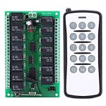
To give a bit of context, I have an old military remotely operated vehicle which I am hoping to restore the basic functions of. The original electronics were completely beyond any use and had been bodged and mated with all sorts of controllers over the past 30 years and no longer worked at all. Having spoken to someone else who has undertaken such a task, they recommended that many of the functions can be controlled using one of these (image also attached to this post): DC 12V 15 Channel Relay Wireless Remote Controller Switch Transmitter + Receiver Board 10A for Large Power Appliances : Amazon.co.uk: Electronics & Photo
My knowledge of radio communication and the relationship between frequency and antenna type/length etc is fairly limited, so I was hoping to seek some clarification before I start removing the original antennas on both the transmitter and receiver and soldering on coax, different antennas etc. According to the specs on the amazon page, the receiver and transmitter is described as having: "Operating Frequency: 315 (Optional From 315 To 433MHz)".
1. When it is described as Operating Frequency: 315 (optional from 315 to 433MHz)" does this mean the frequency is anywhere between between these parameters as standard or is this something that can be changed by modifying the length of the already fitted coil antenna on the receiver?
2. I plan to extend the receiver antenna to be outside the main chassis of the ROV and utilize one of the unused external BNC fittings which are already present, to this I plan on attaching a 315MHz helical whip antenna. Would this be as simple as removing the existing coiled wire antenna, and soldering in a length of coax to bridge the gap between the receiver and the new antenna fitted externally to the vehicle?
3. I also intend to do something similar to Question 2 with the remote transmitter, and contain the remote in a more durable housing with a better antenna than the cheap telescopic one fitted. Could this also be achieved by using coax to connect to a more durable antenna with the same frequency of the receiver antenna?
I look forward to any comments or help that can be provided.
Regards,
Dan