Resources for building first directional antenna/yagi?

Status
Not open for further replies.

ScubaJungle

Active Member
Joined
Mar 11, 2020
Messages
618
Location
West Central Florida
I'd really like to improve my performance on 162-174mhz & 406-420mhz (ideally 115-172 &380 -470, but that may be too wide of a range?), and while I considered buying two yagis but the prices add up quickly.

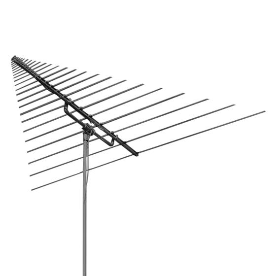
I've been looking for some basic info to get started on building directional antennas/yagi/log periodics, but a lot of the stuff either just shows the antennas without much background info, or are highly technical, and I am not a radio engineer. I've had a surprisingly difficult time finding good, simple, and clear instructions on how to construct one.

Can anyone point me to some links/sources to start off?
I think my best bet is building two, one for the VHF freqs (162-174, or 115-174 if possible) and one for the UHF freqs (406-420, or 380-470 if possible)

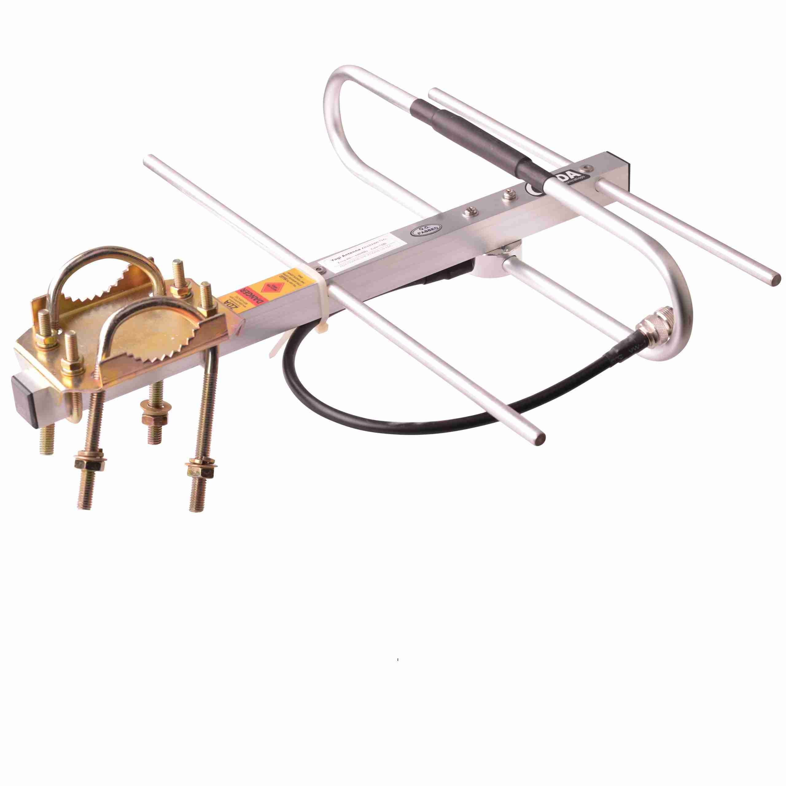
I was considering buying this:

but if I can save money, and have something to do, I think it would be worth it.
I found this for length:

but I'd like to get some more info regarding:
-most efficient materials to use for the elements. I see some people use tape measures, some use copper wire, etc. If I am going to build it, I want it to be worth it and efficient.
-how wide of a range I can make it vs efficiency
-basic plans/blueprints
-anything else - would it be worth it to make a log periodic and have a wider range with a single antenna, or go with the two?

Any other beginner resources for constructing an antenna/yagi properly.

Thanks
 

prcguy

Member
Joined
Jun 30, 2006
Messages
15,333
Location
So Cal - Richardson, TX - Tewksbury, MA
Sounds like you really need a log periodic. Here is an online calculator that should work. The basic construction could be two square booms 1" wide running the full length of the antenna. You could use 1/4" dia aluminum rods for the elements with a 1/4" through hole to fit them in the boom then drill and tap a 4-40 hole in each element about 3/4" from the end and put a screw through the boom into each element.

I punched in 115Mhz for the low end and 470MHz for the high end and using the default settings it gave me reasonable dimensions for the elements and boom with 14 elements and a 3 1/2ft long boom. It says you need a a 1ft terminating stub a the rear of the antenna so you make the booms a little over 1ft too long and short them out 1ft from the rear of the antenna. You could also make the booms another 6" longer and attach to a plate to end mount the antenna.

With these instructions and the junk I have on hand I could probably turn one out in an afternoon. Log‑Periodic Dipole Array Calculator
 

ScubaJungle

Active Member
Joined
Mar 11, 2020
Messages
618
Location
West Central Florida
Sounds like you really need a log periodic. Here is an online calculator that should work. The basic construction could be two square booms 1" wide running the full length of the antenna. You could use 1/4" dia aluminum rods for the elements with a 1/4" through hole to fit them in the boom then drill and tap a 4-40 hole in each element about 3/4" from the end and put a screw through the boom into each element.

I punched in 115Mhz for the low end and 470MHz for the high end and using the default settings it gave me reasonable dimensions for the elements and boom with 14 elements and a 3 1/2ft long boom. It says you need a a 1ft terminating stub a the rear of the antenna so you make the booms a little over 1ft too long and short them out 1ft from the rear of the antenna. You could also make the booms another 6" longer and attach to a plate to end mount the antenna.

With these instructions and the junk I have on hand I could probably turn one out in an afternoon. Log‑Periodic Dipole Array Calculator
Thats what I was thinking as well, they just seem very complicated for a first antenna. Thanks for that website, at least the the lengths are doable - I will just have to figure out how much it will cost. If it's going to cost any more than $200, then I might as well buy this:
but hopefully, I can keep it below there.


The aluminum rods seem simple enough and pretty cheap, but what would you suggest using for the boom and terminating stub? Im going to have to find a good document that dissects a log-periodic because Im not even familiar with a terminating stub, but as long as I know what material to look for I can figure the rest out.
From my limited understanding so far, it seems Ill need:
14-15 aluminum rods
~4.5' boom
~1.3' terminating stub
bolts, nuts, coax
Is there any major concept or piece that Im missing?
At the moment, I only have access to a hand drill, but it seems like that will be enough for this
ALso, if Im going to go that route, I might as well make it even wider and go up to 800mhz to get public safety, right? I have a 800mhz yagi, though, so its not necessary.

Heres the calculation for 100mhz-900mhz:
INPUT
Lowest frequency f₁ = 100 MHz
Highest frequency fₙ = 900 MHz
Diameter of the shortest element ⌀ = 6 inch
Characteristic input impedance Zc_in = 50 Ω
Taper τ = 0.880
Optimal relative spacing σₒₚₜ = 0.163
Chosen relative spacing σ = 0.060

RESULTING DESIGN
Number of elements ⌊N⌉ = 21
Dipole element lengths:
dipole ℓ₁ = 4.918 ft
dipole ℓ₂ = 4.328 ft
dipole ℓ₃ = 3.808 ft
dipole ℓ₄ = 3.351 ft
dipole ℓ₅ = 2.949 ft
dipole ℓ₆ = 2.595 ft
dipole ℓ₇ = 2.284 ft
dipole ℓ₈ = 2.010 ft
dipole ℓ₉ = 1.769 ft
dipole ℓ₁₀ = 1.556 ft
dipole ℓ₁₁ = 1.370 ft
dipole ℓ₁₂ = 1.205 ft
dipole ℓ₁₃ = 1.061 ft
dipole ℓ₁₄ = 0.933 ft
dipole ℓ₁₅ = 0.821 ft
dipole ℓ₁₆ = 0.723 ft
dipole ℓ₁₇ = 0.636 ft
dipole ℓ₁₈ = 0.560 ft
dipole ℓ₁₉ = 0.493 ft
dipole ℓ₂₀ = 0.433 ft
dipole ℓ₂₁ = 0.381 ft
Sum of all dipole lengths ℓₜₒₜ = 38.185 ft

Distances between the element centres
and their position along the boom:
d₁,₂ = 0.590 ft, i.e. ℓ₂ @ 0.590 ft
d₂,₃ = 0.519 ft, i.e. ℓ₃ @ 1.109 ft
d₃,₄ = 0.457 ft, i.e. ℓ₄ @ 1.566 ft
d₄,₅ = 0.402 ft, i.e. ℓ₅ @ 1.969 ft
d₅,₆ = 0.354 ft, i.e. ℓ₆ @ 2.323 ft
d₆,₇ = 0.311 ft, i.e. ℓ₇ @ 2.634 ft
d₇,₈ = 0.274 ft, i.e. ℓ₈ @ 2.908 ft
d₈,₉ = 0.241 ft, i.e. ℓ₉ @ 3.149 ft
d₉,₁₀ = 0.212 ft, i.e. ℓ₁₀ @ 3.361 ft
d₁₀,₁₁ = 0.187 ft, i.e. ℓ₁₁ @ 3.548 ft
d₁₁,₁₂ = 0.164 ft, i.e. ℓ₁₂ @ 3.713 ft
d₁₂,₁₃ = 0.145 ft, i.e. ℓ₁₃ @ 3.857 ft
d₁₃,₁₄ = 0.127 ft, i.e. ℓ₁₄ @ 3.984 ft
d₁₄,₁₅ = 0.112 ft, i.e. ℓ₁₅ @ 4.096 ft
d₁₅,₁₆ = 0.099 ft, i.e. ℓ₁₆ @ 4.195 ft
d₁₆,₁₇ = 0.087 ft, i.e. ℓ₁₇ @ 4.282 ft
d₁₇,₁₈ = 0.076 ft, i.e. ℓ₁₈ @ 4.358 ft
d₁₈,₁₉ = 0.067 ft, i.e. ℓ₁₉ @ 4.425 ft
d₁₉,₂₀ = 0.059 ft, i.e. ℓ₂₀ @ 4.484 ft
d₂₀,₂₁ = 0.052 ft, i.e. ℓ₂₁ @ 4.536 ft
Boom length L = 4.536 ft

Length of the terminating stub ℓ_Zterm = 1.229 ft
Required characteristic impedance of the feeder
connecting the elements Zc_feed = 36.4 Ω
 

prcguy

Member
Joined
Jun 30, 2006
Messages
15,333
Location
So Cal - Richardson, TX - Tewksbury, MA
A hand drill won't cut it, you really need a drill press and a drill press vice to hold the elements when you drill and tap them. The boom material can be 1" square aluminum tubing. A 115 to 470MHz version looks easy to me but when you get up to 900Mhz lengths get critical and the overall antenna will be more complicated.

Its too bad KMA Antennas is no longer in business, they had some well made Log Periodics for very good prices. The Create logs are ok but the gain is way hyped, they are more in the 5dBd gain range.

Thats what I was thinking as well, they just seem very complicated for a first antenna. Thanks for that website, at least the the lengths are doable - I will just have to figure out how much it will cost. If it's going to cost any more than $200, then I might as well buy this:
but hopefully, I can keep it below there.


The aluminum rods seem simple enough and pretty cheap, but what would you suggest using for the boom and terminating stub? Im going to have to find a good document that dissects a log-periodic because Im not even familiar with a terminating stub, but as long as I know what material to look for I can figure the rest out.
From my limited understanding so far, it seems Ill need:
14-15 aluminum rods
~4.5' boom
~1.3' terminating stub
bolts, nuts, coax
Is there any major concept or piece that Im missing?
At the moment, I only have access to a hand drill, but it seems like that will be enough for this
ALso, if Im going to go that route, I might as well make it even wider and go up to 800mhz to get public safety, right? I have a 800mhz yagi, though, so its not necessary.

Heres the calculation for 100mhz-900mhz:
 

ScubaJungle

Active Member
Joined
Mar 11, 2020
Messages
618
Location
West Central Florida
A hand drill won't cut it, you really need a drill press and a drill press vice to hold the elements when you drill and tap them. The boom material can be 1" square aluminum tubing. A 115 to 470MHz version looks easy to me but when you get up to 900Mhz lengths get critical and the overall antenna will be more complicated.

Its too bad KMA Antennas is no longer in business, they had some well made Log Periodics for very good prices. The Create logs are ok but the gain is way hyped, they are more in the 5dBd gain range.
Oh man well good thing I mentioned that and didnt find out the hard way.
That makes sense, I would stick with 115-470 then and that wouldn't be an issue at all. How can you tell about the lengths and how important they are in relation to frequency? Is that something you just know from knowledge of antenna theory/wavelengths or is that something you can tell from looking at that information?

The gains seemed ridiculous, so Im not surprised. Its definitely a bit steep on the pricing too, maybe Ill wait and see what else I can find. I guess better than the $1k+ price tag on many of them. I wish that I could tell how ebay ones are made, but with my limited knowledge I'd be better staying far away from there.
 

Ubbe

Member
Joined
Sep 8, 2006
Messages
9,033
Location
Stockholm, Sweden
I would recommend buying a TV logperiodic antenna and use that as a base, or get longer square tubes for the boom if it's too short and re-use the material from the tv antenna. My local shop has VHF logperiodics for $20 that's 3ft long and then you buy new aluminium rods, and probably needs you to buy a tool to make threads to it and install as in prcguys link.

The distance between elements and their lenght and position from the front of the boom determines the frequency. The more elements you can fit and use a smaller frequency range the more gain you get and a more directional antenna.

Logperiodic antennas use a technique that only the elements that resonate to the frequency are active, the others are ignored, and the more elements in the general frequency that can resonate the more gain it will give. If you makes an antenna from 100MHz-900MHz with a 3ft boom it will probably only be two or perhaps three elements that will be active at a frequency and still be efficient enough to give a 3-5dB gain above a dipoles.

If you don't need gain between 200Mhz and 400MHz then you can make the antenna dual band, that some tv antennas are. Make one calculation for the UHF band using the frequency range you want and desirable gain and only state half of the boom lenght and then make another calculation for VHF, but double the highest frequency and the gain, that uses the full boom lenght but only use the measurements that starts after the UHF elements and to the end of the boom. The last and longest element only works if it has that extra stub lenght to the boom. Or you can have a shorter stub and do like Create does and have that same lenght in solid metal wire like a coil at the end so the total lenght from wire and boom to the last antenna element are the same as in the calculation.

As the distance between elements are shorter at UHF they will give higher gain using the same boom lenght as VHF uses. If you need more VHF gain then state a shorter boom lenght for UHF. The elements lenght tip to tip are a 1/2 wave so you can adjust your input in the calculator until you'll see that the upper VHF range equals to the second VHF elements lenght to get some gain. In metrics the wavelenght are 300 divided by the frequency in MHz and then divide by 2 to get a 1/2 wavelenght in meters and multiply by 100 to get centimeters, or 39,5 to get inches.

s-l225.jpg


/Ubbe
 
Last edited:

ScubaJungle

Active Member
Joined
Mar 11, 2020
Messages
618
Location
West Central Florida
I would recommend buying a TV logperiodic antenna and use that as a base, or get longer square tubes for the boom if it's too short and re-use the material from the tv antenna. My local shop has VHF logperiodics for $20 that's 3ft long and then you buy new aluminium rods, and probably needs you to buy a tool to make threads to it and install as in prcguys link.

The distance between elements and their lenght and position from the front of the boom determines the frequency. The more elements you can fit and use a smaller frequency range the more gain you get and a more directional antenna.

Logperiodic antennas use a technique that only the elements that resonate to the frequency are active, the others are ignored, and the more elements in the general frequency that can resonate the more gain it will give. If you makes an antenna from 100MHz-900MHz with a 3ft boom it will probably only be two or perhaps three elements that will be active at a frequency and still be efficient enough to give a 3-5dB gain above a dipoles.

If you don't need gain between 200Mhz and 400MHz then you can make the antenna dual band, that some tv antennas are. Make one calculation for the UHF band using the frequency range you want and desirable gain and only state half of the boom lenght and then make another calculation for VHF, but double the highest frequency and the gain, that uses the full boom lenght but only use the measurements that starts after the UHF elements and to the end of the boom. The last and longest element only works if it has that extra stub lenght to the boom. Or you can have a shorter stub and do like Create does and have that same lenght in solid metal wire like a coil at the end so the total lenght from wire and boom to the last antenna element are the same as in the calculation.

As the distance between elements are shorter at UHF they will give higher gain using the same boom lenght as VHF uses. If you need more VHF gain then state a shorter boom lenght for UHF. The elements lenght tip to tip are a 1/2 wave so you can adjust your input in the calculator until you'll see that the upper VHF range equals to the second VHF elements lenght to get some gain. In metrics the wavelenght are 300 divided by the frequency in MHz and then divide by 2 to get a 1/2 wavelenght in meters and multiply by 100 to get centimeters, or 39,5 to get inches.

s-l225.jpg


/Ubbe
Thank you for breaking that down, it makes much more sense now. I saw the TV antennas for cheap and was tempted but wasn't sure if they would be worth the space but that could be a good starting point without shelling out $300+.
I really wouldn't need to include anything above 470mhz, I have a 700-900mhz yagi. My priority of frequencies/gain would be:
(most important)406-420mhz>162-174mhz>115-162mhz>220-400mhz(least)

The only thing I dont understand is:
"The last and longest element only works if it has that extra stub lenght to the boom. Or you can have a shorter stub and do like Create does and have that same lenght in solid metal wire like a coil at the end so the total lenght from wire and boom to the last antenna element are the same as in the calculation."
What are the "stubs"? The only completely labeled diagram I could find shows them as blocking/shorting the UHF portion from the VHF portion?

Im not sure if you have seen my latest thread, but I'm considering just buying more of those dipoles from the rtl-sdr blog and devoting each one to a particular frequency range. I really dont understand why they work so well, but when I put them at the correct length, they beat my discone, my Diamond RH789, and compete with my yagi. I wonder if they would be just as good as/better than this? That also makes me wonder, if I got a larger telescopic dipole with better material, would it work even better? This is the thread, if you have time to weigh in. I appreciate your support and your knowledge about this all!
 

prcguy

Member
Joined
Jun 30, 2006
Messages
15,333
Location
So Cal - Richardson, TX - Tewksbury, MA
A log periodic is a series of dipoles distributed along a balanced feedline. At any given frequency within its range there will be at least three elements in use with one acting as a longer reflector. At some frequency, possibly the lowest usable for the antenna, the stub would cause a reflection back up the feedline. Not sure if that would happen within the operating range to help the longest element that has no reflector or if the stub is tuned out of band for something else. You could use a coil for the stub but most design calculators only tell you the stub length and I have not seen info on making that into a coil.

The only thing I dont understand is:
"The last and longest element only works if it has that extra stub lenght to the boom. Or you can have a shorter stub and do like Create does and have that same lenght in solid metal wire like a coil at the end so the total lenght from wire and boom to the last antenna element are the same as in the calculation."
What are the "stubs"?
 

ScubaJungle

Active Member
Joined
Mar 11, 2020
Messages
618
Location
West Central Florida
A log periodic is a series of dipoles distributed along a balanced feedline. At any given frequency within its range there will be at least three elements in use with one acting as a longer reflector. At some frequency, possibly the lowest usable for the antenna, the stub would cause a reflection back up the feedline. Not sure if that would happen within the operating range to help the longest element that has no reflector or if the stub is tuned out of band for something else. You could use a coil for the stub but most design calculators only tell you the stub length and I have not seen info on making that into a coil.
Thanks, I get the idea now. I didnt realize that there are reflectors for each set of three elements. I got some research to do, that's for sure
 

MUTNAV

Active Member
Premium Subscriber
Joined
Jul 27, 2018
Messages
1,084
So... any ideas about connecting to the feed-line, if I remember right, there was a little coil at the end of an LPDA just prior to the connector.

Thanks
Joel
 

prcguy

Member
Joined
Jun 30, 2006
Messages
15,333
Location
So Cal - Richardson, TX - Tewksbury, MA
The feedline connects to the front or small element end. For the dual boom type one boom goes to the shield of the coax and the other to the center conductor. You really should use a good choke balun at that point and its common to run the feedline up inside the ground side boom but center it with some insulation around the coax so the coax floats electrically. In that case the choke balun would attach at the point where the coax exits the boom.

So... any ideas about connecting to the feed-line, if I remember right, there was a little coil at the end of an LPDA just prior to the connector.

Thanks
Joel
 

MUTNAV

Active Member
Premium Subscriber
Joined
Jul 27, 2018
Messages
1,084
Gotcha... If I remember right on the Create LPDA's there was a coil also on the BACK, the longest element. that connected the two halves together.
Is that needed on the home built LPDA's?

Thanks
Joel
 

Ubbe

Member
Joined
Sep 8, 2006
Messages
9,033
Location
Stockholm, Sweden
A logperiodic antenna are like a self tuning yagi. You have a dipole element and behind that a reflector element and in front of the dipole you have the director elements that increase the gain the more of them you have, exactly like a yagi. But the only active elements will be those that are more or less in resonance with the frequency. At the antennas lowest frequency it will only be a couple of the longest elements that are active, the others on the antenna will be almost isolated from the antenna.

At the antennas highest frequency only the shortest elements at the front will be active. The more elements that resonanate at a frequency the more gain you'll have, but the directivity will be much more and the boom will be much longer.

The two booms should be shorted together at the back end of the boom and will be part of the design. It's probably a matematical electric lenght that are needed from the position of the longest element, perhaps 1/8 wavelenght of the lowest frequency. You can have that lenght mechanicly by the boom lenght or electrically by a wire, wound as a very loose coil with almost no inductance.

It's two booms that works as a balanced antenna and when you connect an unbalanced coax you'll need to decouple the coax shield by a choke. You often see this done by routing the coax inside one of the booms, that will work as a choke for the coax, and it comes out at the back of the antenna where it attaches to a mast pole.

/Ubbe
 

N9JIG

Sheriff
Moderator
Joined
Dec 14, 2001
Messages
5,598
Location
Far NW Valley
The Grove Scanner Beam was a great consumer grade wide-band directional scanner antenna back in it's day. I wish I still had one but I sold it as it would not fit in my attic. I am pretty sure it was a variation on the Log Periodic design.

A friend had one on his tower back in the late 80's with a rotor and it worked great. Connected to his R7000 we spent hours plotting transmitters with it.

If you could get a hold of one of these or recreate one you would be golden.
 

Ubbe

Member
Joined
Sep 8, 2006
Messages
9,033
Location
Stockholm, Sweden
The Grove Scanner Beam was a great consumer grade wide-band directional scanner antenna back in it's day. I wish I still had one but I sold it as it would not fit in my attic. I am pretty sure it was a variation on the Log Periodic design.
I looked at a picture of it and it is a yagi design. It uses a single boom, and cannot be logperiodic, and the front part are designed for the 800MHz band with 4 elements that actually have some gain.
The back part are designed for VHF and UHF and has 4 elements each and are in parallell like a dual band yagi but covers such a huge frequency range that it has hardly any gain left and are almost comparable to a dipole in four different sub bands in VHF and UHF.

/Ubbe
 

ScubaJungle

Active Member
Joined
Mar 11, 2020
Messages
618
Location
West Central Florida
I ended up purchasing another of the telescopic dipoles from my other thread, and Im very happy. They come with a very thin, flexible coax too that makes using it on the BCD436HP very nice and easy to move around. Im able to pick up at least 50% more, probably up to 75% more than I did with the handheld antennas. Obviously, when I am not home they are necessary, but at home this set up is great. The improvement in the VHF and UHF (406-470) ranges is amazing - I was totally unable to pick up a lot of nearby trunked systems on UHF, and forest service, port/marine, etc channels of VHF, and now I am getting all of them regularly.
 
Status
Not open for further replies.
Top