Rolling My Own 8 Port Multicoupler

Status
Not open for further replies.

KC1UA

Scan New England Janitor/Maintenance
Database Admin
Joined
Oct 27, 2002
Messages
2,106
Location
Marstons Mills, Cape Cod, Massachusetts
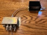
With another upcoming shack renovation pending, I got to thinking (dangerous in and of itself) about my multicoupler situation. I currently use two Stridsberg actives, one a 4 port and the other an 8. I also use 2 Electroline EDA UG-2802's. I've decided to make one of my own based on some information derived from RR.

Components, in order of sequence from antenna to 8 way splitter:

BNC female to SMA male 6" jumper. This is intended to relieve strain from the next component, which is...
FM Broadcast band notch filter. Absolutely required around these parts, and I have had decent luck with these little suckers. SMA male to male barrel gets connected to...
20db Wide Band LNA. This has the PGA 103+ chip design and offers the capability of external DC voltage for power, which in my case is ideal. Its output connects to...
SMA male to F male adapter. This gets things flipped over to RG6 QS with F connector land, which the majority of my receive only application is wired with. Then, on to...
8db inline attenuator. This knocks the gain of the LNA down, and yes I know the LNA gain will vary somewhat over its coverage, but I figured it would be best suited with...
8 way CATV splitter. Self explanatory of course. Each output apparently suffers an 11db loss, so that plus the 8db pad, and taking into consideration everything in line along the way I figure I'm in the ballpark of having little to no gain at each output.

Now, if someone would please tell me what I'm missing, if anything, or add any suggestions, or tell me if I just blew $80 bucks or so for nothing, that would be great. I am considering a variable attenuator instead of the 8db option if necessary. As I will be re-introducing an auxiliary standup rack into the shack config it will be my intention to mount all of this fun stuff on a blank 3u panel in the vicinity of the antenna patch panel I've used for years. Another thing I may have to consider are a few other notch filters but I am going to hold out on them at the outset as they could potentially cause me attenuation issues on bands I like to search for signals on, namely 460-465 MHz where there is a nasty DMR control channel that shows up all over the spectrum in addition to where it actually belongs. I also do realize that the LNA is not in an ideal spot and should be as near to the antenna as possible, but that's not the case with the Electroline or Stridsberg models either. I think this is the same, amplification to overcome the inevitable signal loss when splitting an antenna several ways.

If this works out well I will probably build more of them over time. Any thoughts would be appreciated with my thanks.
 

prcguy

Member
Premium Subscriber
Joined
Jun 30, 2006
Messages
16,351
Location
So Cal - Richardson, TX - Tewksbury, MA
Personally I would avoid cable TV amplifiers, they are designed for closed cable systems with known and constant signals and not for wildly varying off air reception levels. Here is my version of an ideal multicoupler that will put any Stridsberg to shame. Overall gain is between 0 and 1dB from 50 to 1000MHz for eight outputs. 1dB compression point of the amp is 26dBm, IP3 is 46dBm and noise figure is on par with the Stridsberg at 3.5dB. Add an RF limiter to the input that caps the amp at around 10dBm for safety and it should last forever.

Total cost off eBay was under $120.

multicoupler.jpg
 

KC1UA

Scan New England Janitor/Maintenance
Database Admin
Joined
Oct 27, 2002
Messages
2,106
Location
Marstons Mills, Cape Cod, Massachusetts
Thanks for responding. One of the reasons I'm looking for alternatives is that despite the fact they seem to work well I've always been somewhat skeptical of the Electrolines. And on occasion, the Stridsbergs although their customer service when I've had failures has been excellent.

Is the Mini Circuit splitter used due to a capability of high isolation between ports? I can't determine what the amp is, but I like the instructions on the side! :D
 

belvdr

No longer interested in living
Joined
Aug 2, 2013
Messages
2,567
Personally I would avoid cable TV amplifiers, they are designed for closed cable systems with known and constant signals and not for wildly varying off air reception levels. Here is my version of an ideal multicoupler that will put any Stridsberg to shame. Overall gain is between 0 and 1dB from 50 to 1000MHz for eight outputs. 1dB compression point of the amp is 26dBm, IP3 is 46dBm and noise figure is on par with the Stridsberg at 3.5dB. Add an RF limiter to the input that caps the amp at around 10dBm for safety and it should last forever.

Total cost off eBay was under $120.
I'm not a builder b/c frankly I don't know what I'm doing. Is there an off-the-shelf version of something similar?
 

prcguy

Member
Premium Subscriber
Joined
Jun 30, 2006
Messages
16,351
Location
So Cal - Richardson, TX - Tewksbury, MA
If you buy the amp, splitter and a 12V 1A linear wall wart power supply I'll mount it to an aluminum plate and make a double shielded jumper between the amp and splitter and send it back to you.

QUOTE="belvdr, post: 3766165, member: 740286"]
I'm not a builder b/c frankly I don't know what I'm doing. Is there an off-the-shelf version of something similar?
[/QUOTE]
 

KC1UA

Scan New England Janitor/Maintenance
Database Admin
Joined
Oct 27, 2002
Messages
2,106
Location
Marstons Mills, Cape Cod, Massachusetts
Actually I found what I believe is the LNA.


@Ubbe suggested the PGA 103+ in one of the messages I came across here, and I've no doubt that from your ton of posts you have a pretty good idea of what works, so a few different options to consider.
 

prcguy

Member
Premium Subscriber
Joined
Jun 30, 2006
Messages
16,351
Location
So Cal - Richardson, TX - Tewksbury, MA
The PGA103+ chip can be ok for a general purpose preamp but not for everyone and it won't survive in my big city environment without overloading and creating IMD. One of the better versions 0f the PGA103 is the Minicircuits ZX60-P103LN which has great noise figure and good IP1/IP3 specs, but the gain varies from about 23dB at 50MHz to 18dB at 500Mhz then 13.5dB at 1000MHz. That's a 10dB slope in the wrong direction for scanner use.

The ZHL-1010 is flat 10dB gain from 50-1000MHz and much better IP1/IP3 specs but you take a 3dB hit in noise figure. The amp shown above is the ZHL-2010 which is a 20dB gain version and an ok choice if your are splitting 8 ways or more. You don't want to use a 20dB gain preamp feeding just one or a couple of receivers without attenuating the amplifier output, and then it will still be amplifying too much raising signals closer to IMD levels where it doesn't need to. There is always a give and take when choosing amplifiers and there is no perfect solution.

Actually I found what I believe is the LNA.


@Ubbe suggested the PGA 103+ in one of the messages I came across here, and I've no doubt that from your ton of posts you have a pretty good idea of what works, so a few different options to consider.
 

KC1UA

Scan New England Janitor/Maintenance
Database Admin
Joined
Oct 27, 2002
Messages
2,106
Location
Marstons Mills, Cape Cod, Massachusetts
One of the beauties of this type of setup is the component factor. If I don't like the LNA I bought it's easily replaced, and maybe a few tweaks have to happen after that but overall minimal pain.

I am in what I'd call a "suburban" type of RF environment so I will see if the PGA103 holds up. If not I'll search for one of the Minicircuits ZHL models and replace it. The PGA103 setup in my original post was el-cheapo so no worries there.

Thanks again for the information and suggestions.
 

Ubbe

Member
Joined
Sep 8, 2006
Messages
9,646
Location
Stockholm, Sweden
8db inline attenuator. This knocks the gain of the LNA down, and yes I know the LNA gain will vary somewhat over its coverage, but I figured it would be best suited with...
8 way CATV splitter. Self explanatory of course. Each output apparently suffers an 11db loss, so that plus the 8db pad, and taking into consideration everything in line along the way I figure I'm in the ballpark of having little to no gain at each output.

I've tested the PGA103+ at work using a roof mounted 4-stack dipole antenna for UHF and 2-stack for VHF and the tallest building in Stockholm where 200-300 meters away, that had at least 20 transmitters for 2-way radios and of course all cellular operators had a site there as well. I had zero problem with the amp. It was only my scanners that needed to use filters and attenuators to not overload, not the amplifier as I had all filters between amp and scanners.

I would say that 99% of scanner user will have no problem with a PGA103+ based amplifier. It's compression point at its input are 0dBm where problems starts. That's a huge signal level. A very good scanner like BCT15x have at least 20dB worse tolerance to overload and would be the first thing that runs into problem.

A variable attenuator are always the best solution as additional attenuation are dependent of the scanners quality and what filters you use. Amplifiers performance to not overload are better at higher frequencies and the same are true for scanners. The lower the frequency the higher the risk to run into problems. There's also less attenuation thru air at lower frequencies. The PGA103+ has the wrong sloop EQ curve, it amplifies more at lower frequencies and coaxes also attenuates less at lower frequencies.

To fix this you could add a small capacitor in series after the amplifier and before or after the coax. You can usually pry the lid off a CATV splitter and then cut the trace to its input connector and solder a 2pF-3pF capacitor over the cut. It will attenuate 3dB at 800MHz and 10dB at 150MHz and 20dB at 70MHz. If you need low-VHF then 4,7pF will have 12dB attenuation at 40MHz so probably just the splitters added attenuation will be sufficient. I use a 1-6 splitter with high gain 10dBd antennas and use no extra attenuation to the PGA103+, but then a live in a low signal area.

Capacitor value and total attenuation also depends of how much cellular interference it might be in the 700-900MHz range and the coax attenuation. If doing that capacitor fix in a splitter or other device, then solder a 47 or 68 ohm resistor from input to ground to keep a proper coax load, but be careful to not load any bias-T power that might ride on the coax.

/Ubbe
 

garys

Member
Joined
Jun 13, 2002
Messages
6,212
Location
Texas
I'm looking at a similar situation and Scott pointed me to this thread.

prcguy, what do you recommend for the amplifier? Are both items available on Ebay?
 

prcguy

Member
Premium Subscriber
Joined
Jun 30, 2006
Messages
16,351
Location
So Cal - Richardson, TX - Tewksbury, MA
The amp kind of depends on how much RF you have in your area and what frequency range you want. The PGA-103 series or a MiniCircuits ZX60-P103LN can be ok but I don't like its gain drop off as you go higher in frequency. If you only need VHF and UHF through maybe 500MHz there will be about 3-4dB loss in gain going from 100MHz to 500Mhz which is not too bad. If you need to hit 1GHz then the slop is closer to 10dB loss at 1GHz compared to 100MHz. You will also have to attenuated the output depending on how many times you split it since its got well over 20dB gain at 100MHz.

Going to a higher power amp that will work better in high level RF environments like the ZHL-1010 will have a consistent gain from 50MHz to 1GHz but you take a big hit in noise figure. If you were to remote the amplifier at the antenna with a good FM trap filter you will probably make up for the higher noise figure. I've found a few ZX60-P103LN and ZHL-1010 amps on eBay in the $50-$60 range but you have to check often since the go fast. Same with 8-way splitters in the VHF-UHF range, good priced units go fast.

I'm looking at a similar situation and Scott pointed me to this thread.

prcguy, what do you recommend for the amplifier? Are both items available on Ebay?
 

garys

Member
Joined
Jun 13, 2002
Messages
6,212
Location
Texas
Since you show Tewksbury as one of your landing spots, I can give you some more detail.

I need up to 1Ghz and would like to start around 40Mhz so I can catch both the 900Mhz MotoTrbo trunks and the MSP on low band. The former is the higher priority.

I live a bit southwest of Boston and have the Blue Hills between me, Boston, and the northern suburbs.

I really only need five outputs and will cap the rest.

So, based on that, what do you recommend for a pre amp?

I'm on Ebay frequently enough to check at least daily.
 

prcguy

Member
Premium Subscriber
Joined
Jun 30, 2006
Messages
16,351
Location
So Cal - Richardson, TX - Tewksbury, MA
Its hard to recommend something without knowing what your RF levels are. What kind of antenna will you use?

To figure out things like this I usually monitor the entire frequency range with a spectrum analyzer in peak hold mode for several hours mid day to see if there are any major offenders or I'll connect an HP power meter to the antenna and monitor that for average levels over a period of time. If the average levels are down in the -50dBm range or lower then you might get by with a preamp that has an IP1 of maybe 17-22dBm and those can be had with good noise figures in the .5dB range. If your levels are like mine that can reach -10dBm average then even a high level amp like a ZHL-1010 will have problems but hopefully only some of the time.

Then you have to see where the worst offenders are and maybe a band stop filter can reduce those enough where a lower level, lower noise figure amp can be used. Sometimes you have to remove the FM broadcast band or the UHF TV band or some new 5G stuff in the low to mid 700MHz range can be pretty devastating to a preamp. Then you don't want too much preamp gain and for feeding up to an 8-way divider 10 to 15dB gain max would be a good target since a good 8-way divider has about 9.5dB loss.

If you have too much gain like 25-30dB then its going to run the preamp into IMD range that much faster. For example if you have a bunch of signals that add up to -50dBm combined, a 10dB gain amp will run them up to about -40dBm if the amp is operating in its linear range. Put a 30dB gain amp in the same setup and now its outputting around -20dBm and even if the amp has a 1dB compression point of 1 watt its still going to produce some unwanted IMD. Even if you attenuate the output the amp is still seeing levels that will produce IMD in its output stage.

I literally have boxes of preamps here that will not work at my place on a wide band antenna. I have one odd mystery amp with way too much gain that works surprisingly well and the ZHL-1010 does ok here, but most fail miserably. I usually test preamps while listening to distant VHF and UHF ATIS stations where most preamps will make reception worse with a higher noise floor (usually lots of IMD) and noisier reception. When I finally find a good one the reception will sometimes be very slightly better or about the same quality but with a larger signal level to then feed a divider. A preamp near the radio like in a multicoupler will never make any magic reception changes unless you have a very numb receiver that is starving for level and the preamp specifically addresses that. For most modern receivers the improvement in signal quality takes a back seat to the additional gain needed to overcome divider loss in a multicoupler.

So you have some homework to do before you can make a good decision on what amplifier is best.

Since you show Tewksbury as one of your landing spots, I can give you some more detail.

I need up to 1Ghz and would like to start around 40Mhz so I can catch both the 900Mhz MotoTrbo trunks and the MSP on low band. The former is the higher priority.

I live a bit southwest of Boston and have the Blue Hills between me, Boston, and the northern suburbs.

I really only need five outputs and will cap the rest.

So, based on that, what do you recommend for a pre amp?

I'm on Ebay frequently enough to check at least daily.
 
Status
Not open for further replies.
Top