jjlongworth
Member
Warning - technical discussion ahead
I've worked in electronics for over 40 years and I've been scanner enthusiast for even longer. So, this isn't my first rodeo. I have a 436, which is an amazing scanner, and have successfully used the GPS feature in it since new. Rather than go the puck route, I chose to use a DeLorme PN-20. It was cheap and it allows me to still use the GPS features (i.e. speed, distance etc) while scanning. This has worked fine for years. As soon as you plug in the scanner, the GPS text appears on the display immediately regardless of the satellite status.
I also have a HomePatrol 1 that works with this setup. However, I should point out, that the GPS text doesn't appear until the GPS has a lock on the satelites.
To use the PN-20, I needed to make an adapter to breakout the necessary signals from the GPS: RXD, TXD and GND. Although I've read that only TXD and GND signals are required, I also connected RXD. The information for the gps side was well documented. The scanner side was a little trickier because it used the unique Hirose brand connector. Nevertheless, I found the pinout for the scanner and this setup worked perfectly.
Here's where it gets interesting: I recently purchased an SDS100. I'm not quite as thrilled with the SDS as I had hoped, but that is for a different post. One of my complaints would be the fact that they eliminated the Hirose connector and integrated the functionality into the mini USB (bad idea). Instead they added a Mico USB that, to my knowledge, has no functionality. But I digress...
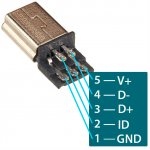
Since the days of being able to find a good reference like SAMS Photofact are long gone for most things, I turned to the internet. I found a couple of posts on RR that mentioned the pinout for the mini USB plug on the side of the SDS. They've said that it is wired as a standard mini USB (looking at the back of the connection from left to right):
Pin 1 = GND
Pin 2 = ID
Pin 3 = D+
Pin 4 = D-
Pin 5 = V+
I've confirmed the pinout and the USB functionality works fine. I am able to program and charge the unit without any issues. I've read that since there are only two signals required (GND and TXD) for the GPS, that they used the unused ID pin for the TXD input. On principal, I hate mixing signals types on connectors to produce a "non standard" cable, but armed with this info, I made a cable similar to the one I use for the 436.
Take my word for it, I have checked my connections multiple times and I have confirmed that both devices are set for DMS DD:MM'SS.ss and 4800 baud. Something is different between these scanners. I could have a defective unit, but would find it hard to believe. It is supposed to be serial data, so we're not blazing a new trail here.
I could have just bought the puck and be on my way, but something is different between these two applications. Either there is a firmware issue or there is something different about the hardware internal to the scanner. Any ideas?
I've worked in electronics for over 40 years and I've been scanner enthusiast for even longer. So, this isn't my first rodeo. I have a 436, which is an amazing scanner, and have successfully used the GPS feature in it since new. Rather than go the puck route, I chose to use a DeLorme PN-20. It was cheap and it allows me to still use the GPS features (i.e. speed, distance etc) while scanning. This has worked fine for years. As soon as you plug in the scanner, the GPS text appears on the display immediately regardless of the satellite status.
I also have a HomePatrol 1 that works with this setup. However, I should point out, that the GPS text doesn't appear until the GPS has a lock on the satelites.
To use the PN-20, I needed to make an adapter to breakout the necessary signals from the GPS: RXD, TXD and GND. Although I've read that only TXD and GND signals are required, I also connected RXD. The information for the gps side was well documented. The scanner side was a little trickier because it used the unique Hirose brand connector. Nevertheless, I found the pinout for the scanner and this setup worked perfectly.
Here's where it gets interesting: I recently purchased an SDS100. I'm not quite as thrilled with the SDS as I had hoped, but that is for a different post. One of my complaints would be the fact that they eliminated the Hirose connector and integrated the functionality into the mini USB (bad idea). Instead they added a Mico USB that, to my knowledge, has no functionality. But I digress...
Since the days of being able to find a good reference like SAMS Photofact are long gone for most things, I turned to the internet. I found a couple of posts on RR that mentioned the pinout for the mini USB plug on the side of the SDS. They've said that it is wired as a standard mini USB (looking at the back of the connection from left to right):
Pin 1 = GND
Pin 2 = ID
Pin 3 = D+
Pin 4 = D-
Pin 5 = V+
I've confirmed the pinout and the USB functionality works fine. I am able to program and charge the unit without any issues. I've read that since there are only two signals required (GND and TXD) for the GPS, that they used the unused ID pin for the TXD input. On principal, I hate mixing signals types on connectors to produce a "non standard" cable, but armed with this info, I made a cable similar to the one I use for the 436.
Take my word for it, I have checked my connections multiple times and I have confirmed that both devices are set for DMS
DD:MM'SS.ss and 4800 baud. Something is different between these scanners. I could have a defective unit, but would find it hard to believe. It is supposed to be serial data, so we're not blazing a new trail here.I could have just bought the puck and be on my way, but something is different between these two applications. Either there is a firmware issue or there is something different about the hardware internal to the scanner. Any ideas?