The mighty mighty exposed dipole array wins again

Status
Not open for further replies.

prcguy

Member
Joined
Jun 30, 2006
Messages
15,336
Location
So Cal - Richardson, TX - Tewksbury, MA
I recently came across a deal on a couple of UHF exposed dipole arrays to replace a dual band amateur antenna in repeater use. The dual bander is a copy of the Diamond X510 series, about 17.5ft tall with a VHF rating of 8.3dB and UHF of 11.7. I've been running this antenna on a UHF amateur repeater at my house for the last year and have mapped out its coverage fairly well, which is ok but not stellar. I also have a temporary use 2m repeater at my house and have used the VHF side of this antenna on the repeater with similar results, ok but not great.

One of the UHF dipole arrays I picked up has two 4-bay dipoles on the same mast with separate feedlines and since the dipoles are arranged in a row the gain is right around 9dBd with an elliptical pattern of maybe 100 to 120deg wide at the -3dB points. This is ok for my location due to the large hill on one side of my house and anyone using the repeaters would be away from the hill.

I took some precise receive measurements on the Diamond X510 clone before taking it down then compared to one of the UHF 4-bay dipole arrays after it went up. I was surprised to see signal strengths on some line of sight repeaters coming in between 5 and 6dB better on the 4-bay dipole array compared to the 17.5ft dual bander that supposedly has 11.7dB gain on UHF. 11.7dB over what? If its dBi then it would be 9.56dBd but that doesn't explain why an actual 9dBd gain antenna is 5 to 6dB better.

After the 4-bay UHF antenna has been up for a month I'm getting great reports of better signal strength in all areas and people can now use the repeater in areas where they couldn't before. This is a huge and unexpected increase in coverage from swapping out a 17.5ft antenna for an 8ft tall antenna, although the 4-bay is raised up to the same height as the top of the old 17.5ft.

I'm so happy with the improvement I dug out some Cushcraft VHF 2m dipoles I've had for years that were part of a 4-bay dipole array but I never had the mast or coax phasing harness. I refurbished the dipoles, built a 24ft aluminum mast out of some decommissioned antennas and built a coax phasing harness out of 75ohm TV coax and F connector T adapters. Today I completed this VHF 4-bay dipole array but not before putting the 17.5ft Diamond X510 clone, taking some precise receive measurements and find the new VHF 4-Bay dipole array is between 3 and 4dB better on the 2m ham band when mounted in the exact same spot.

So if the Diamond X510 clone is rated at 8.3dB and my new 4-bay VHF is 3 to 4dB better and cannot be more than 9dB, that means the X510 clone is really around 5dBd gain. So where do they get the 8.3dB rating? Bottom line here is the 4-bay dipole array is a winner and has the most gain you can get for its size. They are also pretty easy to make, so if you want some big performance ditch your foreign fiberglass crap and put together a 4-bay dipole array. You can find instructions for a VHF version in post #5 here: 4-bay VHF dipole array project

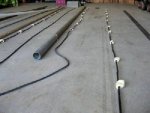
Here is a picture of my new VHF dipole array project with a lot of TV coax hanging off the back side.

1638321023418.jpeg
 
Last edited:

alcahuete

Member
Premium Subscriber
Joined
Jul 24, 2015
Messages
2,488
Location
Antelope Acres, California
Don't know what the gain is or where they get the rating, but my X510 is by far the best VHF/UHF antenna I have ever used, outside of Yagis. Been up for over 20 years without a bit of maintenance, or preventative anything prior to putting it up. Works like the day I bought it.
 

vagrant

ker-muhj-uhn
Premium Subscriber
Joined
Nov 19, 2005
Messages
3,177
Location
California
Come on now, even I know if you spread those 4-bay dipoles in a 360° pattern...anyways why did it take you so long to convert to that? Have you been RF cooking the worms out of the soil on the hill for fishing or what?
 

prcguy

Member
Joined
Jun 30, 2006
Messages
15,336
Location
So Cal - Richardson, TX - Tewksbury, MA
I can't make use of a 360deg omni pattern here so 120deg will work just fine. And its 3dB more gain in that mode over omni. I got a bunch of radio checks tonight on 2m simplex and with my 125w base radio people in areas I didn't expect to get into are giving me S9 +60 readings.

Come on now, you know if you spread those 4-bay dipoles in a 360° pattern...anyways why did it take you so long to convert to that? Have you been RF cooking the worms out of the soil on the hill for fishing or what?
 

vagrant

ker-muhj-uhn
Premium Subscriber
Joined
Nov 19, 2005
Messages
3,177
Location
California
Nice...by the way, the local club here is soon to get several acres of donated property a hair under 7000' up on Tehachapi. I should be able to work you during a VHF contest after we take ownership. Probably the June and September stuff, so I can avoid snow during January contests. I'll be crushing the airwaves with 10 watts or less. ( It's almost 93 miles at a 9° bearing from your QTH ) I don't think I have tested 900 MHz handhelds that far yet. I may need to use the yagi and 10W.

I'll probably camp up there even during non contest weekends as well. Too much was burned here in central California last year and displaced seasonal visitors will probably take over my fun contest spots that are still green. I'll give your repeaters a try as well from there if you want, but it should work from 7k.
 

tweiss3

Is it time for Coffee?
Premium Subscriber
Joined
Apr 24, 2020
Messages
1,077
Location
Ohio
I love your write up. Does this have any coverage over 70cm as well?
 

kk9h

Member
Premium Subscriber
Joined
May 4, 2006
Messages
65
Location
Northfield, IL
I would guess that the X510's 8.3dB rating is "dBi" not "dBd" which is typical of antenna specs in ham product advertising. My club has a similar Decibel antenna on our 440 MHz repeater. It is an offset pattern typed rated 9dBd in the direction of the elements from the mast, 6dBd off both sides and 3dBd toward the back.
 

900mhz

Member
Joined
May 13, 2005
Messages
432
I have been using a DB420 for UHF...so far nothing can touch it...set up in an omni pattern. It hears and gets out better than any type of stationmaster type antenna.
 

900mhz

Member
Joined
May 13, 2005
Messages
432
Which brings up another question...I have yet to find a folded dipole array for 700/800 MHz...similar to a DB408 or 420 but for the 700/800 band.
I always wondered why.
 

prcguy

Member
Joined
Jun 30, 2006
Messages
15,336
Location
So Cal - Richardson, TX - Tewksbury, MA
Which brings up another question...I have yet to find a folded dipole array for 700/800 MHz...similar to a DB408 or 420 but for the 700/800 band.
I always wondered why.
I believe the Bogner 800 antennas are dipole arrays inside a fiberglass radome. I've had some other interesting 800 dipole arrays that were stamped out of galvanized steel sheet metal then stuck inside a PVC radome. They looked very cheap to mfr. I put one on the RR classifieds years ago and nobody asked about it over a several month period so I threw it away.
 

900mhz

Member
Joined
May 13, 2005
Messages
432
I found a couple of 800 MHz sticks in my garage...7/16 DIN connectors. Going to try to see what exactly they are. I do know they did not see much action time wise when mounted. I guess they were removed due to system changes. I happened to be there when the tower crew was replacing them at a main state site. They were mounted for about 10 months or so.
 

studgeman

Member
Premium Subscriber
Joined
Dec 19, 2002
Messages
687
The gain numbers do not tell the whole story nor just the horizontal pattern which you reference. You also have to factor in the vertical pattern, that would likely explain the difference between the antennas. How wide is the main vertical lobe, and how much reduction do you get in the subsequent lobes. Depending on your coverage goals from a particular location and antenna height, you have to balance the vertical and horizontal patterns. Take a look at this sheet from Comprod for UHF dipole series. Its a good illustration at how the patterns can change. Comprod UHF Dipoles
 

900mhz

Member
Joined
May 13, 2005
Messages
432
The gain numbers do not tell the whole story nor just the horizontal pattern which you reference. You also have to factor in the vertical pattern, that would likely explain the difference between the antennas. How wide is the main vertical lobe, and how much reduction do you get in the subsequent lobes. Depending on your coverage goals from a particular location and antenna height, you have to balance the vertical and horizontal patterns. Take a look at this sheet from Comprod for UHF dipole series. Its a good illustration at how the patterns can change. Comprod UHF Dipoles
No doubt...HAAT, gain, ERP, license. Certain antennas (or perhaps exclusion of antennas) come into play.
 

prcguy

Member
Joined
Jun 30, 2006
Messages
15,336
Location
So Cal - Richardson, TX - Tewksbury, MA
I forgot to mention some info on making a phasing harness for this type antenna. In the "4-bay dipole array project" link above, that project antenna is centered around 153MHz and its phasing harness calculations center it around the same frequency. Its best to start with a calculation of three or five 1/4 wavelengths with velocity factor, then test and tune the length with an antenna analyzer.

This is really easy because an open ended cable made of odd length 1/4 wavelengths shows up as a short on an antenna analyzer. Just calculate, cut a little long, install one connector and find the resonant point near your target frequency. The cable should be too long, so start trimming until the zero ohm point is on your target frequency. As you trim the cable see how much taking a 1/4 or 1/2" off affects the frequency because you want to cut the cable slightly short because the T adapters used in the phasing harness will add length.

So if cutting an inch off equates to .5MHz, then measure the length of one side of your T adapter, estimate how much that will affect the cable and cut that much off. The cable will now null out on the antenna analyzer a little high in frequency but when the phasing harness is all put together it will be right where you want it transferring the match of each dipole through the harness to the common input connection without skewing the match of the antenna array.

The reason I'm mentioning this is because if your making a 2M specific antenna like I just did, the phasing lines will be longer than in the project antenna link above.
 

tweiss3

Is it time for Coffee?
Premium Subscriber
Joined
Apr 24, 2020
Messages
1,077
Location
Ohio
Your last post, and previous write up were very helpful. I've been mauling this over as a project to try, as you can never improve your antennas too many times. I do have a few questions.

1) Is there a calculator for the spacing between the dipole and spacing off the mast? I see you used 57" in the writeup.

2) I had an interesting conversation last night with another local ham about an antenna he bought years ago. It sounded like two "folded dipole" antennas on the same mast, similar to the 8 element DB420, with the 4 element VHF dipole at 90 degrees to the UHF elements. It works really well for him. Being that the comscopes are a pair of folded dipoles 180 from each other, the 90 degree spacing makes sense. Since this above design uses a vertical dipole on one side of the mast, I would think it would be better place the VHF and UFH elements 180 degrees from each other. This is of course providing the 90 degree rotation at each to make the array omnidirectional. Are these correct assumptions?

3) Do you have a better list of part numbers for the tees/fittings? I know the PDF had parts, but you indicated you found better options for building this phase harness.
 

prcguy

Member
Joined
Jun 30, 2006
Messages
15,336
Location
So Cal - Richardson, TX - Tewksbury, MA
I don't remember where I got the dipole spacing but probably from a commercially made antenna of the same frequency range. The spacing is close to a full wavelength but not quite. I also see other 2m specific dipole array projects that use 60" spacing center to center on the dipoles. That is also a bit less than a full wavelength.

The DB Products dipoles use a pair of dipoles 180deg apart times four sets which probably fills in the omni patter better but its twice as many dipoles and a more complicated phasing harness to make. If you asking about stacking a VHF and UHF dipole array on the same mast that would be a problem because if you start the first UHF dipole at the top opposite the VHF, the spacing will be different between the bands and at some point the dipoles will bump into each other at some compass heading.

For this recent 2m project I purchased some cheap generic F type T adapters off Ebay and used a combination of RG6 for the long cables and Belden 1505A for the connections to the dipoles because my dipoles had SO-239s and the 1505A cable has a braid that can be soldered. All other connections were F connectors. If I were to do this again I would consider using mil type RG-11 with copper braid and make my own junctions without connectors by soldering the mating cables to a small copper sheet that I could roll up around the connections and tack solder together for better shielding. That would let the cables enter and exit opposite each other so it lays down nice on the mast where a T adapter leaves one cable sticking out in the air and you have to bend it back town to the mast.

I also had some problems with this recent project where I used hot glue heat shrink on all the T adapters. I checked the entire antenna with phasing harness before heatshrinking and it was perfect, then after heatshrinking it had a really bad match. Turns out the heat gun damaged one or more of the cheap F type T adapters and I had to order another set.


Your last post, and previous write up were very helpful. I've been mauling this over as a project to try, as you can never improve your antennas too many times. I do have a few questions.

1) Is there a calculator for the spacing between the dipole and spacing off the mast? I see you used 57" in the writeup.

2) I had an interesting conversation last night with another local ham about an antenna he bought years ago. It sounded like two "folded dipole" antennas on the same mast, similar to the 8 element DB420, with the 4 element VHF dipole at 90 degrees to the UHF elements. It works really well for him. Being that the comscopes are a pair of folded dipoles 180 from each other, the 90 degree spacing makes sense. Since this above design uses a vertical dipole on one side of the mast, I would think it would be better place the VHF and UFH elements 180 degrees from each other. This is of course providing the 90 degree rotation at each to make the array omnidirectional. Are these correct assumptions?

3) Do you have a better list of part numbers for the tees/fittings? I know the PDF had parts, but you indicated you found better options for building this phase harness.
 
Last edited by a moderator:

merlin

Active Member
Joined
Jul 3, 2003
Messages
2,506
Location
DN32su
Very nice. this design just can't be beat if you don't mind weak off the back side.
They have a nice cardioidal pattern.
I had a Phelps Dodge factory made UHF version on a repeater and the best antenna for the job.
They made a folded dipole counterpart ( DB420 I believe) with the same specs.
The Diamond X510 is a full omni multi element vertical much like the better built super station master.
 

prcguy

Member
Joined
Jun 30, 2006
Messages
15,336
Location
So Cal - Richardson, TX - Tewksbury, MA
A Station Master is 1/2 wave elements with 1/2 wavelength in coax phasing stubs between each element and single band. The Diamond and most others are maybe a 5/8 wave element on the lower band and a multiple of that on the higher band with some goofy zig zag wire thing between each element to make sure they are all fed in phase. I think there are so many compromises getting multiple bands and a good match that something must suffer like the radiation pattern or gain.

There has to be a reason why an 8ft four element UHF dipole array greatly outperforms a 17.5ft dual band collinear on the same frequency. On VHF I'm comparing the 17.5ft antenna to a 24ft 4-bay dipole array and the 24ft wins by 3 to 4dB but that 17.5ft would have to be a good 35ft tall to improve by 3dB using the same design.

Very nice. this design just can't be beat if you don't mind weak off the back side.
They have a nice cardioidal pattern.
I had a Phelps Dodge factory made UHF version on a repeater and the best antenna for the job.
They made a folded dipole counterpart ( DB420 I believe) with the same specs.
The Diamond X510 is a full omni multi element vertical much like the better built super station master.
 

merlin

Active Member
Joined
Jul 3, 2003
Messages
2,506
Location
DN32su
The Super Station Master I was talking is like 23 foot long and like a dozen 1/2 wave sections and 1/2 wave top stub. Matching was a series section, 75 ohm stuffed into the base. Not the best shot of the innards:
There were some problematics with this antenna if not vertically separated.
The high currents made duplexing a chore.
 

Attachments

  • StaMstr_12.jpg
    StaMstr_12.jpg
    138.4 KB · Views: 26
Last edited:
Status
Not open for further replies.
Top