Bought a set of 3 Realistic FM Intercoms from eBay. Great condition all bagged abd boxed and instructions too
Can’t get them working though and after reading the following post I think I’ve figured out why

 forums.radioreference.com
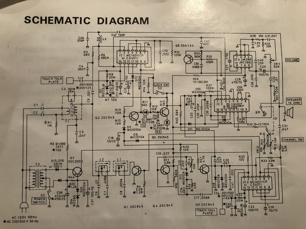
Seems they transmit through the power cables
I’m on the uk 240v 50HZ AC
To power these I’ve had to buy step down transformers 110v/60hz
I’m now guessing the transformers are killing the signal going through the house power cables
No call tones … no nothing
Any ideas?
Turns out when I half pull out the plug and touch the other units plug pins to the one half plugged in it does in fact work but it is then technically a wired unit
Transformer definitely stopping the transmission
Apologies these are Realistic Model 43-214
Can’t get them working though and after reading the following post I think I’ve figured out why
Old School Realistic (Radio Shack) Intercom ???'s
Old School Realistic (Radio Shack) Intercom ???'s (Pic Added) Picked up a working pair of these at a local thrift store. It was a gamble at $25, but when I got them back, I realized they were 5-watt tx power and they actually worked. I think these things are circa 1970. What kind of range...
Seems they transmit through the power cables
I’m on the uk 240v 50HZ AC
To power these I’ve had to buy step down transformers 110v/60hz
I’m now guessing the transformers are killing the signal going through the house power cables
No call tones … no nothing
Any ideas?
Turns out when I half pull out the plug and touch the other units plug pins to the one half plugged in it does in fact work but it is then technically a wired unit
Transformer definitely stopping the transmission
Apologies these are Realistic Model 43-214