I got a PM asking me how to connect two Kenwood TK-X180 mobiles to do cross band repeat.
I've been meaning to reply to that. Since I had to do one today, I thought I would write
this up and put it on the forum for anyone who would like this. It's quite simple for
anyone with the least amount of wiring/solder skills. Parts required are 2 DB-25 male
connectors, 2 DB-25 hoods, 2 miniature volume pots, 2 5.6K resistors, and a chunk of
shielded cable with at least 4 wires plus drain wire (you need all five).
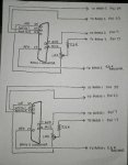
The idea first is to cross two logic lines between radios. I use I/O-1 PTT (to key the
radio) connected to I/O-2 COR or TOR (a receive indicator to key the opposite radio).
This is done on both radios. Second, is to cross receive audio to the mic input of
both radios. Lastly, connect shield wire ground (pin 7) to ground (pin 7).
In this Kenwood radio, receive audio is waaaay too much to put directly into the mic.
I pad the audio down with a 1.0K pot and a 5.6K resistor. The two outside terminals of
the pot connect to MI2 (mic) pin 6 and ME (mic ground) pin 25. The center terminal of the
pot (wiper) goes to a 5.6K resistor. The resistor then connects to the wire that goes to
the receive audio (AFO) of the other radio, pin 17.
In the radio programming, you will need to program I/O-1 (input/output) as input and PTT.
I/O-2 needs to be output, either COR (carrier detect) or TOR (carrier + CTCSS detect).
Both I/O's need to be active low.
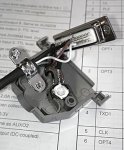
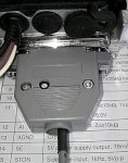
Pic one is the wiring diagram. Pic 2&3 show assembly. I hot glue the pot in place. There
is also a hole drilled into the hood to access the pot for adjustments.
To adjust, turn the pot all the way down. Have someone transmit a test count on one freq,
(have them speak up, no wispering), you listen on the other freq and turn pot until volume
just comes up to max and no more. Usually about a 1/4 to 1/3 turn. Any more and it will
just get more distorted. Swap radios and do the other side. That's it.
This diagram is for an "on all the time" bi-directional repeater, which is what I'm using.
To make it selectable, simply break the two I/O lines between radios and run them up to a
dual pole switch. This would give the user on/off control of the x-band repeater.


