andrewcb88
Newbie
- Joined
- Apr 13, 2019
- Messages
- 1
Hello,
I have been tinkering with things and just trying to come up with a new concept to have a project to do, projects are fun!
So here is what I got:
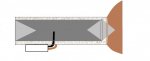
Color coordinated
It's a copper cone attached to a aluminum pipe.
The little copper splashes are suppose to represent copper mesh wire that goes around the tube.
A aluminum inner tube with 2 PTFE convex lens. Starting from the right is a double convex lens, both sides are meant to focus the signal so one going in and 1 going out.
The one on the left is also a convex with a plano back side and goes up against the aluminum tube. Signal comes in, bounces off the back of the aluminum tube and convex PTFE lens refocuses it, to the double convex it goes, where it get's refracted and put back together out the end of the convex PTFE lens.
It's a double antenna wifi card. The black antenna is just your basic antenna, I am going to remove the shell and upgrade the copper wiring and put the shell back on, I don't want it touching other copper parts. The other is just a straight 2 gauge or so wire that goes into the first tube and gets soldered to the mesh which the mesh gets solder to the cone.
The idea is have one antenna for "out" and one for "in". My thinking goes the in will have a larger area to receive signal while the out is more concentrated depending on the convex lens I use(would like to use a lens that makes the signal spread 2-3 degrees)
Now it is time to laugh at my 2D drawing.
Any thoughts?
Thank you,
Andrew
I have been tinkering with things and just trying to come up with a new concept to have a project to do, projects are fun!
So here is what I got:
Color coordinated
It's a copper cone attached to a aluminum pipe.
The little copper splashes are suppose to represent copper mesh wire that goes around the tube.
A aluminum inner tube with 2 PTFE convex lens. Starting from the right is a double convex lens, both sides are meant to focus the signal so one going in and 1 going out.
The one on the left is also a convex with a plano back side and goes up against the aluminum tube. Signal comes in, bounces off the back of the aluminum tube and convex PTFE lens refocuses it, to the double convex it goes, where it get's refracted and put back together out the end of the convex PTFE lens.
It's a double antenna wifi card. The black antenna is just your basic antenna, I am going to remove the shell and upgrade the copper wiring and put the shell back on, I don't want it touching other copper parts. The other is just a straight 2 gauge or so wire that goes into the first tube and gets soldered to the mesh which the mesh gets solder to the cone.
The idea is have one antenna for "out" and one for "in". My thinking goes the in will have a larger area to receive signal while the out is more concentrated depending on the convex lens I use(would like to use a lens that makes the signal spread 2-3 degrees)
Now it is time to laugh at my 2D drawing.
Any thoughts?
Thank you,
Andrew