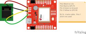
SDS100/SDS200: Uniden SDS 200 GPS Port Pin out.

cshustak

Member
Joined
Dec 7, 2022
Messages
25
I'm trying to wire up a GPS module to my SDS200. My board has VCC, RX, TX, Grnd.
There are four pins in the RJ11 socket on the SDS.

Looking at the socket from outside the radio, how do those pins connect to those four pads on the board, left to right?

Left is toward the antenna jack, and right is toward the power socket.


The pictures on the internet are not clear.

Thanks
 

hexagon_keyhole

Member
Premium Subscriber
Joined
Jul 7, 2020
Messages
275
Location
Sacramento, California
I'm trying to wire up a GPS module to my SDS200. My board has VCC, RX, TX, Grnd.
There are four pins in the RJ11 socket on the SDS.

Looking at the socket from outside the radio, how do those pins connect to those four pads on the board, left to right?

Left is toward the antenna jack, and right is toward the power socket.


The pictures on the internet are not clear.

Thanks
@hagensieker has a nice writeup on their blog about the SDS200 GPS setup and pin outs.


cshustak

Member
Joined
Dec 7, 2022
Messages
25
@hagensieker has a nice writeup on their blog about the SDS200 GPS setup and pin outs.


Is that picture of the socket looking at it from outside in, or inside out? It doesn't seem to match the plug picture that is posted.
The plug picture seems to be looking down on the plug with the locking tab down. The socket doesn't seem to match that.
 

hexagon_keyhole

Member
Premium Subscriber
Joined
Jul 7, 2020
Messages
275
Location
Sacramento, California
Is that picture of the socket looking at it from outside in, or inside out? It doesn't seem to match the plug picture that is posted.
The plug picture seems to be looking down on the plug with the locking tab down. The socket doesn't seem to match that.
I don’t want to hot link photos, but on the first picture “On SDS200,” the view is if you are staring at the exact back of the unit. The RJ12 “telephone cord” plug tab is up.

SDS Orientation:
You are facing the back of the unit. The Antenna plug is to the left, AC Power is on the right.

SDS200 GPS Port is technically a RJ12 jack, 6 position but only 4 contact pins are used and available (6P4C):

Tab Up
Left to Right
3.3v | RX | Ground | TX

On the second photo, Hagensieker is using a RJ11 cable, which is 4 position and 4 contact pins (4P4C) with the tab facing away from you. Since there are no additional pins/contacts available, you can use a RJ11 Cable in the SDS 200.

Tab Down
Left to Right
TX | Ground | RX | 3.3v

GPS Wiring with Tab Down
Left to Right
Out | Ground | In | 3.3v
 

cshustak

Member
Joined
Dec 7, 2022
Messages
25
I got it. The socket needs the tab up on the plug, but the picture shows the tab down to show the wire color. I'll try it tomorrow.
 

cshustak

Member
Joined
Dec 7, 2022
Messages
25
Additional questions.

Does the GPS module antenna have to have vision to the sky in order to work, or can it be under a metal car roof, or in a center console?

Is there a maximum cable length for the GPS dongle to radio?

Other than seeing your location set, is there any other indication that you wired it right, and it's communicating with the radio?

Thanks
 

nessnet

Member
Premium Subscriber
Joined
Jan 22, 2007
Messages
1,936
Location
Eastside of Lake WA
Does the GPS module antenna have to have vision to the sky in order to work, or can it be under a metal car roof, or in a center console?

GPS are radio signals.
Radio signals do not pass through metal.

However, if there is enough GPS signal coming through the windows, then it (may) work.
But, the more satellites it picks up, the more accurate your position will be.
Put it on the dash near the window.
 

nessnet

Member
Premium Subscriber
Joined
Jan 22, 2007
Messages
1,936
Location
Eastside of Lake WA

cshustak

Member
Joined
Dec 7, 2022
Messages
25
Checking to confirm TTL. It's not mentioned in the ad. I also tried 9600 and 4800. No difference.
Should I be seeing something on the 200 display that says it's seeing the GPS?
 

cshustak

Member
Joined
Dec 7, 2022
Messages
25
It is wired right. The Radio +3 to +3 in. Radio TX to GPS RX. Radio RX to GPS Tx and ground.
 

nessnet

Member
Premium Subscriber
Joined
Jan 22, 2007
Messages
1,936
Location
Eastside of Lake WA
It is wired right. The Radio +3 to +3 in. Radio TX to GPS RX. Radio RX to GPS Tx and ground.
If your 200 is receiving GPS data, there is a little GPS icon.
Strongly suggest you edit your display to show lat/long somewhere.

Try switching the TX and RX.
Years ago, I was making GPS cords for a 436.
Must have been over an hour (and %$#!) trying to figure out why it didn't work.
Switched the TX and RX and it worked.
Turns out the cord I was using had them reversed....

Also double check your baud rate (9600 for a 200).
 

kruser

Well Known Member
Premium Subscriber
Joined
Nov 25, 2007
Messages
5,056
Location
W St Louis Cnty, MO
Also double check your baud rate (9600 for a 200).
The baud rate is determined by the GPS device being used. Some can be configured to different baud rates but most seem to be fixed at 4800 or 9600.
Once you know the GPS units baud rate, then the SDS200 or 100 must be set to the same baud rate as the GPS unit.
The SDS200 may use a default of 9600 but that won't play if you hookup a GPS unit that does not use or can't be set to 9600.

I've also used my RJ12 GPS port on my SDS200 as a control port set at 115600 baud in the SDS200 for ProScan control and logging. This was just a test which worked fine but I no longer use it and use IP over LAN instead.
The RJ12 jack on the SDS200 is TTL level I believe so one must be careful with what you plug in. Who knows if the data lines on that port are protected and can handle RS232 serial type voltage levels without damage. You also don't need the TX to GPS line connected for simple GPS location control. Only data from the GPS to the 200 is needed as the 200 does not need to send data to a GPS unit.
 
Top