Where To Solder On A Stereo 3.5mm Jack For Discriminator Tap?

Status
Not open for further replies.

CanesFan95

Active Member
Joined
Feb 14, 2008
Messages
3,014
Location
FL
I've attached a photo. Which prong is ground and which prong is what goes to the tap point in the scanner? I'm assuming one of the 3 prongs will be left unused?

And, can I use a mono 3.5mm cable to plug into the soundcard / data slicer, or do I have to use a stereo cable, or does it make any difference?

Thanks.
 

Attachments

  • Stereo.JPG
    Stereo.JPG
    111.4 KB · Views: 639

Voyager

Member
Joined
Nov 12, 2002
Messages
12,060
Solder the tap to the tip (the connection running to the bent piece). Solder the ground to the sleeve (that might be #3 on your pic - hard to tell).

It looks like two of those connections might run to the same point since there is no ring contact point.
 

CanesFan95

Active Member
Joined
Feb 14, 2008
Messages
3,014
Location
FL
These were advertised as mono plugs when I ordered 'em on eBay, but they came with 3 prongs. So I guess I would just have to manually figure this out from trial and error?
 

rivardj

Member
Premium Subscriber
Joined
Dec 19, 2009
Messages
317
Location
Michigan
The picture you included in your post depicts a closed circuit mono jack. Ground is terminal three and the discriminator tap would go to terminal one. In your Discriminator Tap application terminal two is unused.

This jack would most commonly be used in a mono application where a speaker and headphone/earplug would be involved. The audio feed would be connected to terminal one, one side of the device speaker to terminal two and the ground to terminal three. A ground would also be connected to the other device speaker terminal.

In the described configuration the speaker would play audio with no plug inserted in the jack. Once a plug was fully inserted into the jack, audio would be switched to the headphone/earphone and the speaker would be silenced.

The connections to terminals one and two along with the bent section that contacts the plug tip when plugged into the jack act like a single pole double throw switch.
 
Last edited:

CanesFan95

Active Member
Joined
Feb 14, 2008
Messages
3,014
Location
FL
If I'm drilling a hole into a metal scanner chassis and attaching the socket to the chassis, will that automatically make ground contact so that I wouldn't even need to solder to #3? Thanks.
 

rivardj

Member
Premium Subscriber
Joined
Dec 19, 2009
Messages
317
Location
Michigan
Most likely, yes. However, that would only provide a mechanical connection and could be susceptible to the affects of corrosion and could become intermittent if the jack mounting hardware loosens. Soldering a wire to a ground bus on the board near the jack and then to the jack ground connection would be a more electrically sound connection.
 

rivardj

Member
Premium Subscriber
Joined
Dec 19, 2009
Messages
317
Location
Michigan
I have done many taps with this type of plug 3 goes to tap point 1 goes to ground

Not using the jack in the picture posted by the OP.

His terminal number 3 is definitely the ground terminal. Connecting the tap point to terminal 3 will ground it. The scanner will stop working and may even be damaged.

Look at the OP's picture again, you will see what I am stating is true.
 

Blackswan73

Active Member
Joined
Jan 29, 2015
Messages
1,401
Location
Central Indiana
Use an ohmmeter, or continuity tester. Attach one lead to the curvy part. Touch the other lead to each of the terminals. The one that shows a reading, is the solder terminal for the tap. Now remove the lead from the curvy part. Touch it or clip it to the knurled ring on the jack touch the other lead to the other terminals that did not show a reading before. The one that now gives a reading, is ground.
It appears from the , terminal one is ground, two is the tip, and three is the make/break, which you won't use.
 

rivardj

Member
Premium Subscriber
Joined
Dec 19, 2009
Messages
317
Location
Michigan
Use an ohmmeter, or continuity tester. Attach one lead to the curvy part. Touch the other lead to each of the terminals. The one that shows a reading, is the solder terminal for the tap. Now remove the lead from the curvy part. Touch it or clip it to the knurled ring on the jack touch the other lead to the other terminals that did not show a reading before. The one that now gives a reading, is ground.
It appears from the , terminal one is ground, two is the tip, and three is the make/break, which you won't use.

Good suggestion about using the meter.

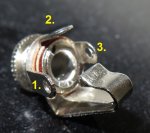
However I do not know what picture you or some of the other contributors are looking at, but clearly in the OPs picture:

1 = Tip
2 = switched terminal - not to be used in this application
3 = ground.

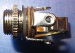
If you look at the picture you will see that:

Terminal 3 is in contact with the tubular section of the assembly. It is sandwiched between the portion of the main body that is peened over to hold the assembly together and the top insulating disk.

Terminal 2 and the switched contact is sandwiched between the top and second insulating disk in the assembly.

Terminal 1 and the tip contact are below/behind the second insulating disk. There is another insulator between the contact and the knurled ring, it is not clearly visible in the picture.

I know how these jacks assembled. I can clearly see how the one in the OPs picture is assembled.

I don't understand how people in this thread are giving such in correct advice. Look at and study the picture the OP posted in post number one. Thankfully we are not dealing with a stereo jack in this case, heads would be exploding all over the place, mine included, but for different reasons.

I will apologize in advance if I have offended anyone with this post, but I am so tired of seeing scenarios like this happen in these forums. Someone gives correct information which answers the OPs question and then a number of arm chair experts with little to no experience/knowledge of the subject matter of the question chime in with their two cents and muddy up everything. If you are not absolutely certain you know what you are talking about don't offer your advice. Don't guess at the answer at the risk of confusing the person looking for help. If you are just out to up your post count, are board and need something to do or just love to type, go to one of the non-technical sub-forums in the Tavern section and strike up a conversation there.

/rant off
 

CanesFan95

Active Member
Joined
Feb 14, 2008
Messages
3,014
Location
FL
Here's a few more close-up shots.
 

Attachments

  • 1.jpg
    1.jpg
    49.7 KB · Views: 406
  • 2.jpg
    2.jpg
    84.5 KB · Views: 375
  • 3.jpg
    3.jpg
    68 KB · Views: 395
  • 4.jpg
    4.jpg
    65.8 KB · Views: 385

rivardj

Member
Premium Subscriber
Joined
Dec 19, 2009
Messages
317
Location
Michigan
Very nice photos.

Absolutely positively put the tap on number 1 and the ground on number three in you original picture.
 

CanesFan95

Active Member
Joined
Feb 14, 2008
Messages
3,014
Location
FL
Understood, thanks!

I am planning to add a 10k resistor and a 10 uF tantalum capacitor in series with the tap. I've always been bad at soldering and always feel I need an extra 1 or 2 hands just to hold two items together while soldering. Soldering is hard and aggravating. I do have a small vice which should help. This is going to be a challenge.
 

rivardj

Member
Premium Subscriber
Joined
Dec 19, 2009
Messages
317
Location
Michigan
Yes, series resistor and capacitor are necessary and it looks like you have the correct values.

Good luck and let us know how things turn out.
 

jaspence

Member
Premium Subscriber
Joined
Mar 21, 2008
Messages
3,041
Location
Michigan
jack for tap

With all the confusion, a new two terminal jack might be a better choice than the conflicting advice. It would be much cheaper than a grounding error.
 

slicerwizard

Member
Joined
Sep 19, 2002
Messages
7,643
Location
Toronto, Ontario
With all the confusion, a new two terminal jack might be a better choice than the conflicting advice. It would be much cheaper than a grounding error.
1 = tip (signal / tap point)
2 = switched audio (normally goes to internal speaker / not used for taps)
3 = sleeve (ground)

No conflict. No confusion.
 

CanesFan95

Active Member
Joined
Feb 14, 2008
Messages
3,014
Location
FL
Well, I'm planning on doing this mod to 3 different scanners and hopefully I'll have time to do at least 1 this weekend. Perhaps I'll post a few photos of how it goes. The first scanner I do will be a Realistic PRO-2006. It's the oldest scanner of the 3 that I have, so if I botch it, at least it's not as big of a loss (even though I know the PRO-2006 is a somewhat sought-after older scanner).

Then it's a BC780XLT and then a BCT15X. The PRO-2006 will be sort-of a sacrificial lamb for learning purposes. I really don't wanna mess up the other 2 newer scanners.
 
Status
Not open for further replies.
Top