Why 'certain' scanners get wiped out by FM broadcast..

Status
Not open for further replies.

Boatanchor

Member
Joined
Jul 17, 2011
Messages
991
I've wondered for a while why certain scanners are so susceptible to interference from FM broadcast on the VHF bands when connected to an external (mobile or base), broadband antenna.

Many of us enjoy monitoring the VHF aircraft bands or the LMR/Ham bands between 108-220Mhz.
In many cases, the signals we are trying to receive are distant and weak.

In my case, if I connect a PSR-600 and a BCD-996XT to the same base antenna via a splitter, I am often able to monitor weak VHF air/LMR comms signals on the Uniden while the PSR-600 hears nothing at all. Hitting search on the PSR-600 is an exercise in futility as the scanner stops every few Khz or so on what sounds like FM broadcast interference. However, If I then connect an FM trap inline, immediately the PSR-600 springs to life and begins to act somewhat 'normally'...

The trouble with FM traps, is that all of them, no matter how much money you spend, also attenuate the bottom end of the aircraft band.

I've suspected for a while that this phenomenon was due to inadequate band/high pass filtering within the GRE RF design. The following attempts to show why this occurs and hopefully, scanner manufacturers will take notice and improve future designs..

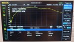
The following photo depicts the front end filtering characteristics of the PSR600 and PSR500 scanners when on the 108-230Mhz band. Note that there are actually five front end band/high pass filters in the GRE scanners covering the 27-54Mhz, 108-230Mhz, 220-400, 400-512 & 750-1300Mhz ranges.

The problem with the GRE scanners on VHF, is that the 108-230Mhz 'filter' offers no protection at all from FM broadcast signals in the 88-108Mhz band.

The spectrum analyzer plot below, depicts the front end filtering characteristics of the PSR600.
Marker '1R' is centered on 150Mhz, as a reference point. The point we are interested in, is marker '1'. Marker '1' is located at a frequency that is 6dB down in level from the main filter passband. In the PSR5/600, the 6dB point is at 75Mhz! Why the rolloff of this filter was selected so low in frequency is beyond me. Anyway, even 6dB is not very much attenuation when it comes to reducing very strong signals.

In other words, when the PSR5/600 is tuned to a frequency within the 108-230Mhz range, the scanners front end bandpass filtering is allowing everything from 75Mhz and up, to pass through to the pre-amp transistor unimpeded. This is a major problem, because very strong FM signals being applied to this pre-amp transistor can then produce blocking and or Inter-modulation products that will interfere with what we want to listen to. Unbelievably, there is absolutely no attenuation of 88-108Mhz frequencies in the GRE PSR5/600 scanners!

So, now we know..

Hopefully, in future designs, manufacturers will spend a little more time getting the bit behind the antenna socket right, before they move on to the bells and whistles sections.

There really is no excuse for such an oversight. Was it simply laziness on the part of the designers, or was it due to cost cutting? Either way, improving these front end filters could have been achieved with a simple band-reject filter and less than $1 worth of SMD parts..
 

Attachments

  • P1040868.JPG
    P1040868.JPG
    175.4 KB · Views: 634

zz0468

QRT
Banned
Joined
Feb 6, 2007
Messages
6,034
That level of filtering might be effective for image suppression, and not much more. I suspect the real problem is the specific devices that are chosen as 1st amp and mixer stages. Some devices are far more immune to overload than others.

I'm curious as to how, exactly, you made that measurement. That really doesn't look like any sort of filter response. When I make a measurement that looks like that, the first thing I do is do a sanity check to see where I've gone wrong.
 

Mike_G_D

Member
Joined
Dec 19, 2002
Messages
1,241
Location
Vista, CA
Some years ago a technically competent member who apparently had access to the necessary test equipment posted similar test results although he claimed the GRE's had a low pass filter on the front end thus lacking ANY low end roll off (short of that contained within the front end amp design itself of course). Your results are interesting to me in that they actually are BETTER than I expected! I am surprised that the GRE design even has as many front end filters as you found (five)! In any case, that past poster claimed to have tested both the GRE and Uniden front ends and found that the Uniden had multiple filters with separate band pass filters for the FM broadcast band and the VHF air and High LMR bands but that, again, the GRE only had a low pass filter for the VHF High band (rather than a band pass). Of course, maybe he was right, and the roll off you see is so poor at the low end simply because it is in fact meant solely as a low pass filter and the low end "roll off" is just a result of ancillary matching circuitry, etc.

What many fail to understand, however, is that there is in fact another element of importance in this problem - that of the RF amp's dynamic range. Your filters can only protect you so much; besides out-of-band strong signals there are in-band strong signals to contend with and, once again, the GRE design fails miserably in this regard relative to the Uniden design. For example, where I am, I do not suffer from out-of-band strong signal overload but I do suffer from in-band strong signal overload due to very strong paging systems within the VHF-High band. Outside of a notch filter you cannot filter said signals out. You are now at the mercy of the front end dynamic range. A properly designed RF amp should have decent enough dynamic range so as not to go into compression when confronted with in-band strong signals. There's always a limit, of course, and RF engineering as in all engineering involves compromises. But, given the performance I have noted with the current GRE designs, I have come to the conclusion that while Uniden figured out the lowest cost design they could get away with and went with that, GRE figured out the lowest cost design they could get away with and then took it down a few more notches - BEAN COUNTERS RULE AND ENGINEERS BE DAMMED!

Anyway, I have posted so much about this and other aspects of consumer level scanner radio design compromises (in all manufacturers' designs) in the past that I pretty much gave up expecting the manufacturers to listen to me a long time ago - of course it is a niche market and the profit margin is probably miniscule anyway so I think I expected way too much. However, one iota of a glimmer of hope did come in the form of Uniden including an "IF Exchange" in their scanners some years ago - something that literally floored me! I had thought of such a beast many years ago and, I think, I posted about it if not on the old trunkedradio.net then on the old strongsignals websites. I was really surprised when Uniden actually put that in their radios! Of course, few users understood its usage and it wasn't really well documented in the manuals as to what it did so it is largely ignored or overlooked by most. That was a neat trick to deal with IF image interference issues. Anyway, I thought that was at least one good spot of hope.

Then I saw that the GRE's actually included a real narrow filter in their high end digital scanners when they finally came out (the now "old" PSR500 and PSR600). Again, an unexpected but pleasant surprise! Well, sort of - till I found the extremely bizarre limitations of how it was utilized; you could only use it when programming a frequency in memory mode and could not activate it while in any search mode. Also, though you could engage it ("NFM" mode) in software or using the keypad for P25 mode it wasn't actually used - the wider filter was always used when decoding P25 signals. I confirmed this all with my own tests and then heard from an admin on here who had a contact within GRE that confirmed it. My guess is that the narrow IF filter had corrupting group delay issues or some other problem that badly affected proper P25 decoding so they elected not to make it usable in that mode. But they somehow forgot to inform the firmware and software teams so the soft switch was still in place - impotent for P25 use but still there. And I never did understand why they wouldn't let it engage in search mode! There is one weird issue with its use that I noted that may be the reason but I won't go into it here.

Anyway, now, finally, one of the biggest pet peeves I had with the later Uniden design was their IF filtering - AAARRRRGGGHH!! Decent front end (at least relative to the GRE...which, actually, ain't that hard to be!) but a wide as a barn door IF filter! Yech! Drove me nuts when I finally got a BCT15 that I intended to use for CDF monitoring with the newer 7.5KHz spaced +/-2.5KHz deviation FM channels and I couldn't effectively use it because of the horrendous adjacent channel rejection! Now it's relegated to low band CHP use. I did see your posts regarding changing out the filter and think they were fantastic!!! I intend to try that on my unit if at all possible if my situation can allow it - then I would finally be able to use it for what I originally bought it for! In any case, astoundingly, they LISTENED! The newest models now have, as you and others have discovered, real narrow IF filters to use! Yeah! 'Course I have no money to spend on the hobby anymore so can't buy one of them but, hey, they did really do it!! I AM impressed! Dribbles, I guess, but we take what we can get.

I see one of the problems, besides the poor market relative to other more "sexy" consumer electronics devices, being the desire of most users for the "bling" of "features" which can be, to the delight of the bean counters, relatively easily included in the design as they rely primarily on digital electronics which are far and away easier and cheaper to deal with than "that hory old messy RF plumbing stuff"! More digital "bling" brings in the customers so we can sweep the ugly RF stuff under the rug! As you say and I wholly agree with, the more that average users are aware of and properly informed of what really constitutes good RF performance the more, one hopes, that they will pressure the manufacturers to present better performing RADIOS! I am SOOO tired of hearing how folks want scanners to be pea sized and do Dc-to-daylight like their tiny pocket all-band receivers which seem to do "just peachy" - when connected to what amounts to a bloody dummy load - but nobody wants to even face trying even remotely to understand what a superheterodyne receiver is (ain't a hard concept to grasp, folks, seriously, think about MIXING!) or what the difference is between RF front end performance and IF selectivity! The only thing people seem to grasp is that old horse, "sensitivity"! Make it more "sensitive"! Bring in more "stuff" from "further away"; got news for ya, folks, sensitivity is probably the EASIEST performance point to meet AS LONG AS you neglect everything else (you know, all that messy stuff you don't want to hear about like dynamic range, P1dB, third order intercept, etc.) and make it pass major sensitivity tests in a screen room with shielded coaxial cable and near perfect 50 ohm terminations! Out in the real world in a messy RF environment - well, that's your problem, you wanted the sensitivity and the "bling" so, hey, we delivered! And PLEASE, stop moaning about not being able to make it "selective" (kind of another misnomer as, in the labs I worked in at least, when we talked about "selectivity" it was in relation to IF adjacent and alternate channel rejection while the front end performance in terms of rejection of images and 1/2 IF stuff and so forth was the province of dynamic range, P1dB, etc. and front end filtering [and some interstage filtering, of course]) and "sensitive" at the same time - jeeeze! You design for USABLE sensitivity as dictated by budget and pcb design space requirements and what parts you can have access to (a neglected possible reason, I think, for some of the odd design compromises we see is, I postulate, due to "special relationships" between the parent company and various parts suppliers, but I digress...slightly); "usable sensitivity" meaning how sensitive it is in the presence of a real "polluted" RF environment. Personally, I'll take some loss in "sensitivity" to get a better real receiver that works well on Earth in the middle of downtown Urbania rather than a super sensitive one that works fine only when in a screen room or out in deep space beyond the heliosphere!!

Sorry...I am tired and jaded from going over this so many times in the past to deaf ears (or blind eyes). But, again, I see glimmers of hope in those few real RF features I mentioned above that the manufactures actually did deign to include and efforts of others like yourself - Bravo, Sir, I applaud you! - to bring it all to the reluctant hobbyists' attention! I really am with you in this and seriously hope you can stir the pot - it sure as Hades needs that stirrin'!

One thing, though, I am wondering how you managed to tap into the front end filtering stages? Did you break the connection (pcb trace) between the front end filters and the front end amp and tap in a 50 ohm semi-rigid for connection to the spectrum analyzer? For note, I would have found the best 50 ohm point (at some point where the filters may have been matched to the amp, etc.) and cut the line as cleanly as possible at that point (a 50 ohm microstrip trace?), scrape a little resist off and then attach a short piece of semi-rigid with solder (very short center conductor to trace and outer shield to ground surrounding the microstrip trace). Then attach a sig gen to the antenna terminals and sweep the response with the spectrum analyzer or, better yet, calibrate a network analyzer and attach between S11 and S22 terminals.

-Mike
 

Mike_G_D

Member
Joined
Dec 19, 2002
Messages
1,241
Location
Vista, CA
zz0468, ahhh, ya beat me to it! That's what I get for gettin' all riled up and long winded!;-)

-Mike
 

Boatanchor

Member
Joined
Jul 17, 2011
Messages
991
The plots were obtained by injecting a -20dBm sweep generator signal directly into the antenna port and then 'sniffing' the input of the pre-amp transistor by tapping into the circuit with an appropriate coupling capacitor. There may well be a little impedance mismatch going on, along with a little additional low frequency roll off caused by the coupling capacitor itself, but the basic response curve of the input filter should approximate what is really going on.

The response on the output side of the pre-amp was the same, albeit at ~20dB higher level of course.

The 27-54Mhz bandpass filter by comparison, appears quite good. I will post a screen grab of that too, if anyone is interested. Using the same methodology as above, it depicts a relatively clean/tight bandpass filter characteristic that actually matches the intended coverage quite well.

And yes, there are a lot of factors that contribute to good, or poor strong signal handling. Front end, band pass filtering is only the first line of defense.

I have actually considered replacing the single 21.4Mhz 2nd IF crystal filter with a 4 or 6 pole version. In theory, Increasing the selectivity and ultimate rejection of this filter should have a dramatic impact on receiver performance too. There's probably not much that can be done to improve with the 'barn door wide' SAW filter/s :)

It may even be worth replacing the pre-amp transistor in the mobile versions, with a low noise, high IP3 monolithic amplifier such as a PGA-103+. But alas, there are only so many hours in the day :)

Anyway, the basic idea is to try and bring these issues to the attention of end users so that hopefully, the manufacturers will be a little more compelled to allocate more time and effort into these 'unspoken' aspects of their products in future.
 

fwuffy

Member
Joined
May 25, 2009
Messages
6
Veery interesting. How accessible are the front end filtering components? Hopefully they aren't all buried under epoxy goop. Anyone with a copy of the service manual CDROM care to share the portion of the schematic upstream of the preamp transistor? It would be interesting to run some SPICE simulations and explore the possibility of reshaping the filters.
 

zz0468

QRT
Banned
Joined
Feb 6, 2007
Messages
6,034
zz0468, ahhh, ya beat me to it! That's what I get for gettin' all riled up and long winded!;-)

That was quite a rant! And you zeroed in on my question with the original post in your last paragraph.
 

zz0468

QRT
Banned
Joined
Feb 6, 2007
Messages
6,034
The plots were obtained by injecting a -20dBm sweep generator signal directly into the antenna port and then 'sniffing' the input of the pre-amp transistor by tapping into the circuit with an appropriate coupling capacitor. There may well be a little impedance mismatch going on, along with a little additional low frequency roll off caused by the coupling capacitor itself, but the basic response curve of the input filter should approximate what is really going on.

I think you just made note of some built in inaccuracies in your measurements. Once you have some mismatch to a filter, all bets are off as to what it's response will be. A slight mismatch may be minor, but at this point in time, we're unable to quantify exactly what that mismatch might be. And some filters will be worse than others.

The coupling capacitor will add additional error.

The plot, to me, looks like your coupling roll off on the low end, and maybe the fT of a transistor on the high end. It just doesn't look anything like a good filter response at all.

The response on the output side of the pre-amp was the same, albeit at ~20dB higher level of course.

I would suggest that you re-sweep it, use MUCH less than -20 on the input, like maybe -60, and put one or two gain stages between the output side of the filter and the instrument, as a buffer. You'll be more likely to see what the actual frequency response is, without building in several errors.

The 27-54Mhz bandpass filter by comparison, appears quite good. I will post a screen grab of that too, if anyone is interested. Using the same methodology as above, it depicts a relatively clean/tight bandpass filter characteristic that actually matches the intended coverage quite well.

I'd be quite interested to see that, as well.

I have actually considered replacing the single 21.4Mhz 2nd IF crystal filter with a 4 or 6 pole version. In theory, Increasing the selectivity and ultimate rejection of this filter should have a dramatic impact on receiver performance too.

That might be a very worthwhile improvement.

It may even be worth replacing the pre-amp transistor in the mobile versions, with a low noise, high IP3 monolithic amplifier such as a PGA-103+. But alas, there are only so many hours in the day :)

If there was any way of identifying the device, and determining it's characteristics, that might end up being a relatively easy and effective improvement. I've not modified a scanner like that, but I've certainly replaced enough external preamps with better ones of similar gain, and seen severe intermod problems vanish. I expect the manufacturer would be trying to balance performance with cost, with cost taking a higher priority.

Anyway, the basic idea is to try and bring these issues to the attention of end users so that hopefully, the manufacturers will be a little more compelled to allocate more time and effort into these 'unspoken' aspects of their products in future.

It's an interesting post. I'd like to see what happens when you re-sweep it and couple the analyzer, maybe just before the first mixer. And disconnect the mixer for the measurement.
 

Mike_G_D

Member
Joined
Dec 19, 2002
Messages
1,241
Location
Vista, CA
.....yeah....um, like, what he said!!

-20dBm is quite a lot and just loosely coupling to the point between the filter and amp is a potential source of issues as zz0468 said. A lot depends on the cap's characteristics though I would not expect it to have an SRF in the range we are looking at (though I have no idea what kind and value of cap you were using).

Anyway, another potential problem might be the amp being overdriven with that level and presenting lord knows what kind of load to the filter (maybe - maybe not, a little weird but I've seen some crazy unexpected stuff when amps are overloaded!) which could also affect the results. To me, you really need to isolate the filters from the load and then present them with the load they need to see (they may or may not really need to see a 50 ohm resistive load - there may well be at least some reactive component that may need to be dealt with, dunno, no idea of what these filters are). Again, look closely at the circuit, see the trace between the filter and the RF amp (assuming it is not a buried stripline which presents other problems). Do you see any matching components? Like an L or PI circuit or something. If so, then we have to figure out who needs what kind of load or source impedance. For all we know, at this point, the RF amp presents a reactive funky load when its own output is properly terminated and it itself needs to be matched. Now, lets say the filter was needing to see a complex conjugate of some reactive load and the RF amp, properly terminated itself, whatever that is, needs to see a source of some other complex reactive value. Then, to minimize components, you would likely just match between the two but there might not be a 50 ohm point in that mess at all! In which case, if you now want to test that filter, you would have to break the connection to the matching circuit and then provide your own matching circuit for the test equipment - carefully, as, as zz0468 stated, any mismatch will color your results! Filters can be tricky things to dink around with if you aren't careful in giving them the source and load impedances they really want!

Anyway, I agree that replacing the RF amp with a better choice would almost certainly improve all aspects of performance! However, once again, just swapping out the RF amp with no attention paid to its optimum source and load requirements could yield less than optimum results! If you have access to a network analyzer and can properly calibrate it (at least at 150MHz I wouldn't think that should be too difficult - I spent most of my time working with 820MHz up to 5GHz and the SRF of the components and other factors were pretty "fun" to work with!) then I would strongly advise using that to gather S parameters of the new components and derive optimum matching networks! Even so-called 50 matched "blocks" I never really fully trusted - even if everything is supposed to be a nice and tidy 50 ohm "plug-and-play" Lego set I would first try some tests just to see what they really present and do so under differing conditions (like presenting the RF amp that you choose with all kinds of reactive sources and loads to see what, if any, make it go unstable.

Sorry - I may be a little anal, here. But some attention to such details might be called for.

-Mike
 
Status
Not open for further replies.
Top