Why this loop stick works better?

ofosot69

Member
Joined
Jul 20, 2024
Messages
24
I made a loopstick for my AM radio and I used enameled copper wire of 1 mm (approx) thick to make the loops on a ferrite rod of 1 cm thick and 14 cm long. I made the main loop with the number of turns 4x greater than the coupling loop and that gave a combination of 4:1. But is this a 4:1 loop stick or 8:1?

I even tried the combination of 1:1 and 1:2 turns, but none of them work that great.

I also noticed that only a wire greater than 19 (AWG) gives good resonance.

So, I would like to know why the magic is behind using 4:1 and 19 AWG?

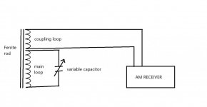
I have attached the setup diagram for reference.
 

Attachments

  • Ferrite Loopstick.jpg
    Ferrite Loopstick.jpg
    30.7 KB · Views: 11

merlin

Active Member
Joined
Jul 3, 2003
Messages
3,072
Location
DN32su
There is no why, RF is strange stuff. If you can tune the main coil high or low at the desired frequency it is resonant.
Your coupling loop will work best when the matching impedance is close/same as the receiver antenna input.
The loops will interact a bit, so your turns ratio is trial and error along with tuning.
 

prcguy

Member
Premium Subscriber
Joined
Jun 30, 2006
Messages
16,157
Location
So Cal - Richardson, TX - Tewksbury, MA
A loop stick should have an amount of turns of primary wire that resonates with a variable capacitor (usually 365pf) then a few turns for the coupling loop. Otherwise it will be untuned and will not work very well. The number of primary turns will depend on the needed frequency range and the size of the ferrite rod and the ferrite mix.

Loop stick antennas are a standard for many AM radios and the main tuning dial on the radio is coupled to the capacitor across the loop stick to resonate it as you tune across the radio spectrum.
 

ofosot69

Member
Joined
Jul 20, 2024
Messages
24
But I haven't got the answer yet---is that a 4:1 loop stick or 8:1? Why the 19 AWG wire works better than the thinner ones?
 

prcguy

Member
Premium Subscriber
Joined
Jun 30, 2006
Messages
16,157
Location
So Cal - Richardson, TX - Tewksbury, MA
But I haven't got the answer yet---is that a 4:1 loop stick or 8:1? Why the 19 AWG wire works better than the thinner ones?
I've never heard of loop stick antenna being rated as a 4:1 or 8:1, etc, they have a lot of turns on the primary to resonate with the tuning capacitor and just a few on the secondary pickup. A loop stick antenna is a resonant antenna and not a balun.

Some people have experimented and found a certain size Litz wire works better at some frequencies than others. Not sure why but many people have tested and experimented and come up with the same conclusions.

Here is a video of a similar ferrite loop antenna I built and I can't find the video showing where he measures the wire inductance so it resonates with the tuning capacitor in the frequency range you want.


ofosot69

Member
Joined
Jul 20, 2024
Messages
24
Yes, but the ratio is for the Main loop turns: Coupling loop turns. Even with a 4:1 turns, it works best and can also be used as a 16:1 matching transformer. I tested on all AM radios and works great. But just asking for 1 help---how do you find the ratio of a matching transformer?
 

prcguy

Member
Premium Subscriber
Joined
Jun 30, 2006
Messages
16,157
Location
So Cal - Richardson, TX - Tewksbury, MA
Yes, but the ratio is for the Main loop turns: Coupling loop turns. Even with a 4:1 turns, it works best and can also be used as a 16:1 matching transformer. I tested on all AM radios and works great. But just asking for 1 help---how do you find the ratio of a matching transformer?
The Youtube guy has another video where he builds the ferrite loop and measures the inductance with a meter to get in the target range for the tuning capacitor then he puts on the coupling loop turns. From what I remember there is about 75 turns on the primary to resonate in the AM broadcast band and only 2 to 4 turns for the coupling loop. There is no 4:1 or 16:1 ratio because its not a transformer, its an antenna.

The 75 or so turns makes a resonant circuit with the tuning capacitor and the coupling turns simply extract the RF from the antenna and sends to the radio, which does not require very many turns and there is no need for an external matching transformer because the 2-4 turn coupling turns is part of the matching.

I built the 16" long ferrite AM antenna from the guys video and that thing brings in stations I could never hear with a stock radio antenna. Another thing it does is if you simply place the ferrite rod and tuning cap near a stock AM radio with built in antenna then tune the ferrite rod it really brings in more stations with no connection to the radio. You don't need any coupling loops for that because the RF field around the ferrite rod antenna couples right to the radio at close range.
 

ofosot69

Member
Joined
Jul 20, 2024
Messages
24
The Youtube guy has another video where he builds the ferrite loop and measures the inductance with a meter to get in the target range for the tuning capacitor then he puts on the coupling loop turns. From what I remember there is about 75 turns on the primary to resonate in the AM broadcast band and only 2 to 4 turns for the coupling loop. There is no 4:1 or 16:1 ratio because its not a transformer, its an antenna.

The 75 or so turns makes a resonant circuit with the tuning capacitor and the coupling turns simply extract the RF from the antenna and sends to the radio, which does not require very many turns and there is no need for an external matching transformer because the 2-4 turn coupling turns is part of the matching.

I built the 16" long ferrite AM antenna from the guys video and that thing brings in stations I could never hear with a stock radio antenna. Another thing it does is if you simply place the ferrite rod and tuning cap near a stock AM radio with built in antenna then tune the ferrite rod it really brings in more stations with no connection to the radio. You don't need any coupling loops for that because the RF field around the ferrite rod antenna couples right to the radio at close range.
I think you didn't get the ratio about a loop antenna. A loop antenna can have a turn ratio when there are two loops---main and coupling. So, 4:1 loop antenna means the main loop is having 4x more turns than the coupling loop. The same concept can be used for a matching transformer but in that case the ratio would mean the primary turns : secondary turns or the formal ratio is 16:1.
 

MUTNAV

Active Member
Premium Subscriber
Joined
Jul 27, 2018
Messages
1,297
This thread might be helpful.


Thanks
Joel
 
Top