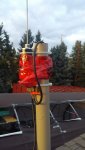
The bracket explains it. Couldn't see that in the photo.
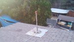
For that base loaded antenna, the best ground plane would be at least 3 x 1/4 wavelength radials pointed about 45 degrees down from horizontal to get a 50 ohm match provided the antenna itself is properly adjusted. Not very practical for what you hope to do. That would be the most efficient, but not required to work reasonably well.
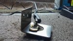
I am not sure what materials you have available, but if you can fashion some other L bracket to mount that bracket directly to the the largest sheet of metal you can place on the roof would work best, but use what you have and see what you get on a SWR meter. Center placement is best, but off center can work. You can adjust the antenna length to offset the impedance mismatch of the flat ground plane. A long time ago I used a 3 foot by 3 foot piece of sheet metal with a mag mount on it for CB and it worked just fine. I don't remember the SWR, but I remember it was pretty good after adjusting the antenna length and range was pretty reasonable.
SWR only needs to be below 3:1 to be effective and keep too much power from being reflected back at the transmitter. Anything below 2.5:1 is most desirable and below 2:1 is very good.
SWR table for reference.
SWR POWER LOSS TABLE
You can also consider making an inverted V out of any available wire. These work quite well and very easy to make. At 4 watts on 27 MHz don't worry about the 1:1 balun you see in most examples.
Inverted V antennas are omnidirectional and very efficient.
Use the below online calculators for 27 MHz. 27.195 is middle band. Best results using 45 degrees down angle for each leg. One attached to the center of coax and the other the shield.
https://m0ukd.com/calculators/inverted-vee-antenna/
Martin E. Meserve - K7MEM - Inverted-V Antenna Calculator